TMDS-Transition Minimized Differential Signaling was first developed by Silicon Image Inc, a Digital Display Working Group member, in 1999. It is a novel method of transmitting high-speed digital data in series. It uses a unique intelligent coding algorithm to reduce electromagnetic interference over copper cables. And it enables clock recovery at the Sink end to achieve high skew tolerance for phenomenal distance cables.
TMDS-Transition Minimized Differential Signaling
Transition Minimized Differential Signaling has high skew tolerance on cables due to its cable designing. This technology is employed in video interfaces used in HDMI and DVI and some other digital communication interfaces.
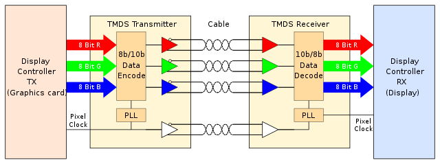
There are two main components employed in Transition Minimized Differential Signaling. They are TMDS transmitter and Receiver. The transmitter and receivers may be separate components or integrated within the graphic and display controller.
TMDS Transmitter and Receiver
It receives 24 bits of parallel data. Once received the data it prepares the data for transmission by encoding and serializing the data. Each RGB color component and clock details are moved forward on different channels. This process is called differential Signaling. Totally there are four differential pairs. The first three are allocated for RGB and the fourth one for transmission of clock data.
Receiver
The Receiver does the opposite process of what the transmitter does at the other end. The Receiver receives the data. It receives the serial data and clock time stamp through the fourth channel and then decodes the data and outs the data in parallel to the display controller.
About TMDS:
The term TMDS stands for Transition Minimized Differential Signaling. Silicon Image Inc. developed it as a two-part system for reducing the chances of transmission gremlins in serial data, mainly video data that serial connection sends. The system has two parts: a physical connectivity part and a software algorithm. In this case, you need to know that the algorithm is used to code and decode the information.
In order to accomplish a target, many theories are put together, and TMDS is the outcome. Let’s learn about some of those theories:
-
It Uses Differential Signaling:
It indicates that over two separate lines which are out of phase with each other, the signal is sent. After getting to the other end, the signals will be merged back into one and eliminate static gremlins that will not have the corresponding out-of-phase signal on the other line.
-
It travels Over Twisted Pairs:
Instead of coaxial cables, twisted pairs will deliver lower electrical interference. An interference that is picked up at a point can get onto a wire and allow this to be removed by differential signalling.
- Rather than having signals compared to ground, it utilizes LVDS, which stands for low-voltage differential signalling. It means that the two signals will be compared to each other instead of to the ground. After doing this, if any spurious noise or signal gets onto a line, it will not really matter as it will be compared to the other one anyway. The comparing circuitry will find the distinction between highs and lows.
- One thing you need to make sure of is that the data that is sent over the line will be DC-balanced. It indicates that the number of bits must match the number of zeroes. The “charge” on the line gets reduced by DC balancing. It helps to resist further changes from ones to zeroes.
- While the data signal has to be DC balanced, it must also be transition minimized. So, the transition number from one to zero will be reduced. As a result, you may experience data loss because of a slow transition from zero to one.
Along with a few specific cable and connector designs, manipulation of the data by the algorithms that can control the TMDS, are required in order to allow all these theories to work together.
Connectivity Requirements
Let’s check the connectivity requirements.
- When it comes to talking about digital video signals, remember that we are talking about a huge amount of data being moved around. The actual 1080p television resolution refers to the 1,920 x 1080 pixels. It indicates that for each screenshot, the data for 2,073,600 individual pixels needs to be transmitted. Television works at 30 fps per second, which means 62,208,000 pixels of information must be transmitted per second. In this case, you should know that every pixel is over 1 byte of information.
A huge amount of data is included in the video signals. Therefore, red, green, and blue, which are the three major color components of video signals, are broken out. Then, these color components are sent separately. These signals are sent out over a shielded pair of twisted pairs.
What Is The TMDS Algorithm Doing?
A computer algorithm refers to a series of instructions that are used to allow the computer to execute something. This one is not a complete computer program, but it is a piece of one. Programs on the computer like a browser or word processing program consist of multiple algorithms. Every algorithm can perform a specific function. Once you tap on the toolbar, it will tell the program what algorithms it needs to use in order to accomplish the function that you want.
The TMDS algorithm can manipulate the data, which is in the byte. Its aim is to make this data easily transmittable, while reducing the risk of damaging the data. Two stages are there in this procedure, and the algorithm selects both automatically. When the data will be transmitted, TMDS adds two control bits to the data byte. Thus, it makes this a 10-bit byte. In order to allow the algorithm to decode the byte, these two bits tell the receiving piece of equipment about the manipulations done to that specific byte.
The target of the TMDS algorithm is to produce a “perfect” byte of information for transmission. An ideal byte theoretically looks like 11111111, followed by 00000000. It helps to produce data that is DC balanced and transition minimized.
- Transition Minimization: It is the first stage of the procedure. In this case, a comparison between the first bit and the bits in the byte is done. Besides, in the first stage, it is determined if a logical XOR or logical XNOR operation would be capable of making the byte to have the least number of transitions.
- Logical XOR = (exclusive or) one or the other. In this case, not both will be a one.
- Logical XNOR =
(not exclusive or), it indicates that both will be one or zero. It is the opposite of XOR. In this case, the “N” term refers to ‘not.’
- DC Balancing: This second stage of the procedure indicates that the whole byte may or may not be inverted in order to balance this with the byte before it.
How TMDS Work:
It uses four channels, namely Red, Green, Blue, and Clock, similar to the traditional RGBHV. It has two-stage processes. The method is of the form 8b/10b encoding in digital logic but using a different pre-defined code-set. The algorithm minimizes the transition to three by doubling up on each transition by adding the 9th Bit and clearing this to a 0 state to show that this 8-bit word was encoded with transitions. With 8b/10b encoding, an additional 10th bit is added to every 8-bit word.
The two-stage process converts the input signal of 8 bits codes into a 10-bit code with particularly desirable properties. This type of process makes the video signal into a significantly smaller one.
Going from eight-bit to ten bits minimizes the transition from zero to one. It is similar to moving from eight Bit ten bits is like changing a smaller word to a larger word ending up in a lesser amount of information. This is the advantage of conversion in data transmission. Therefore the transition minimized differential is very much crucial in signaling. Because of that, TMDS can handle the D4K level of transmission effectively.
Signaling:
The 8- to 10-bit transition minimization and DC balancing performed by TMDS increase the data rate considerably. This algorithm is highly reliable on long and inexpensive copper cables. It reduces the number of transitions, thereby reduce the radio frequency emissions. In turn, it reduces the interference between the source and the sink devices.
TMDS signaling uses twisted pairs of wires to minimize noise reduction and interference rejection called differential Signaling. It is used Current mode logic (CML) or source-coupled logic (SCL). Though it is functional at 5 Volts, the HDMI handshake happens between Source and Sink at 5 volts. But the actual data transfer occurs at 3.3 volts with the help of CML or SCL. The physical layer of TMDS is Current mode logic (CML), or source-coupled logic (SCL), DC coupled and terminated to 3.3 volts. The DATA is DC balanced by the encoding, and the DC coupling is part of the specification.
There are 3+1 twisted pairs for Red, Green, and Blue and the fourth one for sync for the unique 8b/10b Encoding. The transmission happens as a square wave.
The data being sent through the twisted pairs DC balanced lines. The DC balance reduces the electrical charges on the line. It further resists further changes from ones to zeroes.
Further, it is transition minimized. It means; that the number of transitions from one to zero is reduced, thereby eliminating the data loss by a transition.
Hardware Communication
In simple terms, Your Source device, such as Blu-ray or an HD-DVD Player, encodes the input signal to reduce the transitions between one (ON) and zero (OFF). The encoding protects the signal from degrading due to drop-off and delivers the high quality of the signal. Only one of the twisted pairs conducts the signal, and the other carriers carry the inverse copy of the signal. At the receiving end, the sink or the output source, such as your HDTV. It measures the differential or the difference between the signal transmitted and the inverse to compensate for signal loss during the transmission along the line.
The HDMI cables transmit an enormous amount of data. For example, your television resolution is 1920×1080 pixels; then it needs 1920 into 1080 pixels per frame (2, 073,600 pixels). The television refresh rate is 30 frames per second; therefore, it needs to send 2,073,600 multiplied by 30 individual pixels in every second.
Because of this much massive data need to be sent; the main components of the video signals Red, Green, and Blue, are split out and sent separately. For the transmission, it uses 12 pins out of the 19 pins of an HDMI connector. Transition Minimized Differential Signaling technology serves as the primary protocol for both the HDMI and DVI standards. It sends and receives the data at a maximum speed of 225MHz. It enables and supports resolutions up to 2048×1536 in a single link configuration. By using a dual-link solution, you can double the speed to 450MHz.
An algorithm is a set of series of instructions to execute. Every program is made of thousands of algorithms to execute. TDMDS algorithm adds two control bits with the data byte and changes them to 10-bit bytes.
Signal Management:
With the help of those two control bits, the algorithm can be decoded at the receiving end. Its algorithm accomplishes perfect byte information for transmission with the help of those added two control bits. Because of that, the data transmission is transition minimized and DC balanced.
During the transmission, the first Bit is sent untransformed, and each subsequent binary Bit is either XOR or XNOR transformed against the previous Bit. The encoder chooses either XOP or XNOR by determining which will result in lesser transition. And the ninety binary bits encode which one is used in the encoding (XOP/ XNOR). In the primary stage, the first eight binary bits are optionally inverted to even out the balance of ones and zeros to maintain the average DC level. The tenth binary Bit encodes states whether the above said encoding took place or not.
The 10-bit signal can represent either an 8- bit data value during standard transmission or 2 bits of control signal during screen blanking. There are 1024 possible combination can be produced in the ten transmitted bits. Four hundred sixty combinations were utilized to represent 8-binary bit data value. Among these 460 combinations, 256 combinations have two encoded variants.
Some may have the value of only one. 4 combinations are used to represent the two bits control signals (C0 and C1). Since they have some specific properties, they help to synchronize the decoder even if the sync is lost. Two combinations were allocated to use as a guard band before HDMI Data.
The remaining 558 combinations are reserved and forbidden. The characters of the control data are designed to have seven transitions to help the Receiver to synchronize its clock with the transmitter for smooth flow of data.
Pros:
- Transition Minimized Differential Signaling employed in transmitting high-speed serial data.
- It reduces electromagnetic interference over copper cables.
- It enables a more robust clock.
- TMDS uses twisted pair for noise reduction.
- Three twisted pairs are used for data transfer.
- Its DC balancing minimizes voltage swings.
- Noise reduction
- Supports higher resolutions and higher refresh rates
- Delivers Uncompressed Digital Video
Conclusion:
TMDS – Transition Minimized Differential Signaling is a cost-effective digital transferring of data at a more incredible speed in a single link configuration. The band can be increased with the use of second or dual links.
Appendix:
What is Transition Minimized Differential Signaling?
Transition Minimized Differential Signaling is a data transmission method to send digital data from your computer, set-top box, HD-DVD player, or any other video source to a sink example, flat panel Display. It is particularly employed in HDMI and DVI interfaces.
What is DDC?
The Video Electronics Standards Association created the DDC standard. This standard focuses on the better user experience on Plug and Play Gadgets computer displays. Display Data Channel, popularly called DDC, is a bundle of protocols for digital communication between the source example Graphics adapter and the sink example computer display.
This established communication enables the display unit to communicate its supported display modes to the adapter and the adapter to enable the computer to adjust the monitor parameters such as brightness and contrast. It communicates (HDCP (high definition content protection), consumer electronic control (CEC), and Extended Display Identification Data (EDID) between the input device and display unit.
In HDMI, DDC is a communication channel between the input and output device based on the 12C bus specification through which EDID and HDCP data signals are transmitted. Pin 15 and 16 are allocated on an HDMI connector of type A.
What is a Pixel Clock?
The graphic card is constantly sending high-speed pixel data to the display unit. And instruct the display controller when and where the pixels need to be turned ON and OFF. This process is coordinate and streamlined with the help of a pixel clock. The pixel clock guides and instructs the display unit with all information required to light up a pixel row by row and frame by frame. The pixel clock is roughly calculated by multiplying the total number of pixels multiplied by the refresh rate.
Approximately the pixel clock for 1600×1200 at the refresh rate of 60Hz, maybe 115+ MHz. The other factors like blanking time also to be added. The blanking time can be roughly 25 percent of the total pixel clock time. Since the LCD display technology does not have CRT guns, the blanking time is wasted for a digital display. By using reduced blanking and reducing refresh rate, you can achieve higher resolution in a single link.
Clock Recovery:
It is a common system component of digital data transmission over wires, optical fibers, and radio signals. Clock recovery works on serial compressed high-speed digital data transmission. It is a process of extracting time data from a serial data stream to allow the receiving circuit at the sink end and decode it.
Clock Skew:
Time Skew or Clock skew is a term used in synchronous digital circuits; in which clock signal from the source arrives at different times at different components. The immediate difference between the readings of any two clocks is called their skew. In digital transmission, it is caused by many reasons such as wire length temperature variation, device variations within the line, capacitive coupling, and defects in the components. The zero clocks skew refers to the arrival of the source clock edge simultaneously at the transmitting and receiving register.
Negative skew occurred when the register at the receiving end received the clock tick later than the transmitting register. And the positive skew occurs when the receiving register receives the clock tick earlier than the transmitting register. Positive clock skews are good for fixing setup violations. Besides, Negative clock skews are good for fixing a hold violation. But both positive and negative clock skews are inversely proportional.
Differential signaling
Differential signaling is a method of data transmission using two complementary electrical signals. In this method same electrical signal send as a differential pair of signals, each within its Cable (electrical conductor). The pair of conductors are twisted pairs of cables or ribbon cables. In this method, the Receiver responds to the electrical difference between the two signals instead of the difference between each wire and the ground.
This helps you to neutralize the external interference and cancel out the emission interference. In this method, you can reduce electromagnetic noise. It does not affect noise cancellation. Differential signaling needs to be used on balanced lines.
Low-voltage differential signaling:
Low-voltage differential signaling or LVDS is a technological standard that follows the electrical characteristics of serial and differential signaling standards. It is a physical layer specification. But, more importantly, it is a technology standard but not the protocol. Low-voltage differential signaling operates on low power at high velocity using twisted-pair copper cables. LVDS’s typical applications are high-speed video transfer, graphics and video camera data transfers, and computer buses. It works on both parallel and serial transmission.
In serial signal transmission, multiple single-ended signals are serialized into a single differential data pair. The signals send with a data rate equal to that of all the combined single-ended channels. LVDS is a physical layer standard but not Bit encoding scheme. It sends and receives a user-specified encoding scheme that includes 8b/10b encoded data across the cable.
8b/10b encoded data embeds the clock signal data, and it gets the added benefit of Direct Current balance. LVDS is the physical layer signaling to transport bits across cables. It is compatible with all the latest data encoding and clock embedding techniques. In series transmission, it can increase data transmission by grouping multiple LVDS with embedded clock data together.
The destination sink needs to employ data synchronization to align all the multiple serial data channels. It adheres to the industrial standard recommendation of the maximum data rate of 655 Mbit/s over twisted-pair copper cables. High-quality shielded twisted pair cables must be used with elaborate connector systems for cabling for high-quality transmission of 1to 3Gbits/s. LVDS helps you to send and receive uncompressed data through Serial communication protocols at the rate of 3 to 4Gbits /s. Thus it avoids data compression; therefore, you can get the signal delivery at the Sink end without losing image quality and additional latency.