HDMI protocols form the backbone of modern digital AV systems. HDMI signaling architecture enables seamless video, audio, control, and security through a layered and intelligent interface.
-
Introduction
Why HDMI Goes Far Beyond “Just a Cable” — An Overview of Protocol Layers
High-Definition Multimedia Interface (HDMI) has become the de facto standard for digital audio-video connectivity in consumer electronics. However, its significance extends far beyond simply transmitting “picture and sound.” HDMI is a complex layered protocol stack. HDMI signaling architecture unifies several low-level electrical signaling mechanisms, data link protocols, and device coordination systems into a single interface.
“HDMI has become the universal AV language—not because it’s simple, but because it’s standardized and powerful.”
At the physical level, HDMI uses differential pairs, control buses, and auxiliary signal pins. Each one is assigned to a particular subsystem. When you connect an HDMI cable between a source (like a Blu-ray player or GPU) and a sink (like a TV or AV receiver), multiple parallel negotiations and data exchanges occur before a single pixel appears on screen. These include resolution/format detection, HDCP authentication, display timing agreement, control path activation (CEC), and audio routing logic.
The HDMI protocol stack can be broken down into the following layers and signaling systems:
-
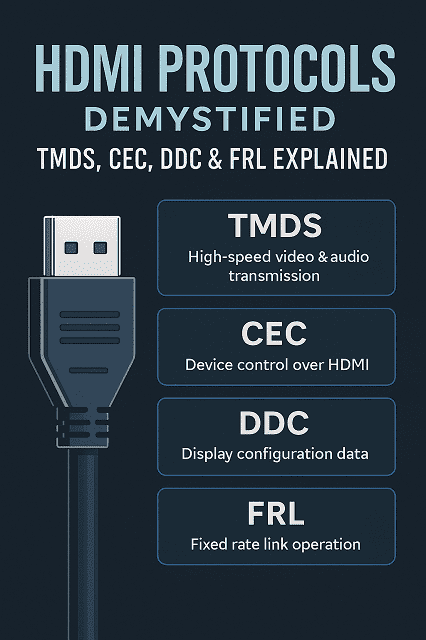
TMDS (Transition-Minimized Differential Signaling)
This is the main high-speed digital data channel responsible for transmitting uncompressed video, multi-channel audio, and auxiliary data (like HDR metadata, audio infoframes, and control packets). TMDS transmits over three data lanes and one dedicated clock channel using differential signaling. It is a key enabler of high-fidelity transmission at rates up to 18 Gbps in HDMI 2.0. The transmission rate increases up to 48 Gbps (with FRL replacing TMDS) in HDMI 2.1.
-
DDC (Display Data Channel)
A bidirectional I²C-based communication link (SCL and SDA pins) is used for reading the EDID (Extended Display Identification Data) from the sink device. This allows the source to determine the display’s supported resolutions, color formats, refresh rates, and audio capabilities.
-
CEC (Consumer Electronics Control)
A single-wire, low-speed bus is shared across all HDMI-connected devices in a setup. CEC allows one device to control another (a TV remote controlling a Blu-ray player or soundbar). It is defined in the HDMI standard. However, it has its own protocol stack (framing, arbitration, device addressing).
-
HPD (Hot Plug Detect)
This signal line is pulled high by the sink device when it is ready for a connection. HPD trigger initialization on the source side. It plays a key role in EDID reading, HDCP negotiation, and link reset events.
-
+5V Power Supply
It is a low-current, 5V line from the source device to power DDC circuitry in the sink, even when the display is in standby.
These channels work concurrently, often with precise timing dependencies. For example, the source cannot send video via TMDS until it reads valid EDID data over DDC. It needs to confirm that HPD is asserted. Further, it needs to complete HDCP key exchange (if encryption is enabled).
Brief Mention of Newer Features Like ARC, eARC, HEAC, FRL
As multimedia requirements evolved, HDMI has adapted by layering in new protocol functions while maintaining backward compatibility:
ARC (Audio Return Channel)
Audio Return Channel was added in HDMI 1.4. ARC allows the sink (usually a TV) to send audio back to the source (AV receiver) over the same HDMI cable. ARC is built on the existing TMDS lines but uses data island periods to reverse audio flow, controlled by CEC signaling. It supports compressed formats (Dolby Digital), but not lossless ones.
eARC (Enhanced ARC)
Enhanced ARC was introduced in HDMI 2.1. eARC uses dedicated differential channels and a new eARC Data Channel (eARC DC) for handshake and status monitoring. It supports high-bitrate audio, including Dolby TrueHD, DTS-HD MA, Dolby Atmos, and DTS:X with up to 192 kHz/24-bit sampling and 5.1/7.1 multichannel formats.
HEAC (HDMI Ethernet and Audio Return Channel)
HDMI Ethernet and Audio Return Channel is an optional HDMI 1.4 feature. It combines ARC with 100 Mbps Ethernet communications between devices. It uses reserved pins (HEAC+ and HEAC−). It requires Category 2 cables. Despite its ambition, HEAC saw minimal adoption due to a lack of industry support.
FRL (Fixed Rate Link)
HDMI 2.1 introduced FRL to replace TMDS when higher bandwidths (up to 48 Gbps) are required. Unlike TMDS’s continuous clocked stream, FRL transmits in bursts of packetized data with Forward Error Correction (FEC) to maintain signal integrity at high speeds. It supports 4K120, 8K60, and even 10K resolutions with Display Stream Compression (DSC).
HDMI is not just a “digital cable,” it is a multiprotocol stack that supports high-speed video transmission, device-to-device control, data synchronization, authentication, and return-channel communication, all over 19 pins. Understanding these layers empowers readers to solve common HDMI issues. However, it also helps professionals optimize systems for performance, compatibility, and longevity.
-
HDMI Architecture & Signaling Layers
HDMI isn’t a monolithic data pipe but rather a layered architectural framework. It is an intricate architectural framework built upon multiple electrical, logical, and protocol layers. Understanding how HDMI is architected at the signal and protocol level provides critical insight into how HDMI signaling architecture achieves synchronized transmission of uncompressed video, multi-channel audio, device metadata, and system control, all over a single 19-pin interface.
Overview of the 19-Pin HDMI Connector: Physical Layer and Pin Assignments
The HDMI connector consists of 19 pins. Each pin is assigned to a specific signal path or channel. These pins are carefully allocated to serve three main purposes:
High-Speed TMDS Channels:
- Pins 1–3: TMDS Data2+ / Data2− / Shield
- Pins 4–6: TMDS Data1+ / Data1− / Shield
- Pins 7–9: TMDS Data0+ / Data0− / Shield
- Pins 10–12: TMDS Clock+ / Clock− / Shield
These differential pairs carry serialized, transition-minimized digital signals, like video, audio, control packets, and auxiliary data. Each channel operates at rates up to 6.0 Gbps in HDMI 2.0.
Control and Utility Channels:
- Pin 13: CEC (Consumer Electronics Control) — single-wire TTL bus
- Pin 14: Reserved for future use (was HEAC+ in HDMI 1.4)
- Pin 15: SCL (Serial Clock Line) – I²C clock for DDC
- Pin 16: SDA (Serial Data Line) – I²C data for DDC
- Pin 17: DDC/CEC/HEAC Ground – shared reference ground
Detection and Power:
- Pin 18: +5V Power – supplied by the source to power EDID logic in the sink
- Pin 19: Hot Plug Detect (HPD), asserted by the sink to indicate presence and readiness
Note: In HDMI 2.1, Pins 14 and 19 can also be used to carry eARC differential signals. It is replacing CEC/HEAC functionality on some implementations.
This meticulous pin assignment supports parallel and independent operation of the video/audio transport, device identification, control plane, and system wake-up functions.
HDMI Operating Modes: Protocol Timing and Channel Coordination
HDMI’s data transmission is synchronized with video timing signals and managed through three primary operating periods. All are carried within the TMDS channels:
-
Video Data Period:
This is when active video pixels are transmitted. Each pixel is encoded into a 24-bit RGB or YCbCr stream (8 bits per channel) and serialized over the three TMDS data channels. The timing matches the pixel clock of the video mode (148.5 MHz for 1080p60).
- Color depth is supported via:
- 24-bit (standard)
- 30/36/48-bit Deep Color (via TMDS clock downscaling and higher TMDS rates)
- Encoding: TMDS uses a proprietary 8b/10b-like encoding scheme with transition minimization and DC balancing. The encoding scheme ensures signal integrity and low EMI.
-
Control Period:
Control periods occur during the horizontal and vertical blanking intervals. This period carries:
- HSYNC/VSYNC (horizontal and vertical synchronization)
- Video blanking codes
- Control signals embedded in the TMDS stream
Control codes are not transmitted as pixel data. Instead, they are transmitted as special control tokens recognized by the receiver’s TMDS decoder.
-
Data Island Period:
This occurs during blanking intervals and is used to transmit non-video data, like:
- Audio samples (IEC 60958 format for LPCM)
- InfoFrames (metadata: audio format, colorimetry, aspect ratio, HDR status, 3D signaling, etc.)
- Auxiliary data (SPD, AVI InfoFrame, Vendor Specific InfoFrame)
Each island is encoded using TERC4 (four-bit ternary run-length coding). It is optimized for reliable data transmission in non-video time.
Clocking Architecture: TMDS Clock Domain and PLL Synchronization
TMDS uses a dedicated clock channel (pins 10 and 11). That operates at the pixel rate for the active video mode. All data lanes are phase-locked to this clock. For Deep Color modes, TMDS decouples pixel rate from data rate by using clock multiplication via PLLs in the receiver:
- 24-bit video: 1x clock rate
- 30-bit video: 1.25x clock rate
- 36-bit video: 1.5x clock rate
- 48-bit video: 2x clock rate
Clock recovery, jitter tolerance, and synchronization margin are critical to avoiding TMDS data errors.
In HDMI 2.1, TMDS is replaced by FRL (Fixed Rate Link) when higher bandwidth is required:
- FRL uses N lanes (3 or 4) with symbol-based encoding and FEC (Forward Error Correction).
- It eliminates the TMDS clock lane and employs packetized timing with embedded synchronization markers.
Signal Integrity Considerations
HDMI signaling at high speeds (especially HDMI 2.0 and beyond) faces serious challenges:
- Impedance mismatches on PCB traces or cable terminations can cause reflections.
- Crosstalk and EMI due to adjacent differential pairs or inadequate shielding.
- Voltage swings are limited (~400–600 mV peak-to-peak) to reduce EMI, increasing sensitivity to loss.
- Equalization and pre-emphasis are used to compensate for channel loss in long cables.
This has led to the adoption of:
- Active HDMI cables with built-in signal conditioners.
- Redrivers and retimers in source/sink devices to restore timing margin and signal quality.
- Certified Premium High-Speed HDMI cables to ensure compliance at 4K60/18 Gbps data rates.
Interdependence of Layers
It is important to realize that HDMI layers are interdependent:
- TMDS cannot function until DDC completes EDID exchange.
- CEC device discovery may depend on the proper HPD status.
- HDCP (encryption) runs over DDC and requires a valid TMDS clock for frame-level encryption/decryption.
- eARC handshakes rely on sideband channels (eARC DC) that share or repurpose existing pins.
Any failure in low-level signal integrity or protocol handshake can prevent the entire link from working, even if the cable or ports appear fine physically.
Initialization Sequence (Simplified)
Here is what typically happens when you plug an HDMI cable into a display:
- Sink asserts HPD (Pin 19 high) to indicate readiness.
- Source applies +5V (Pin 18) to power DDC pull-ups.
- Source reads EDID via DDC (Pins 15/16).
- If HDCP is enabled, then the source and sink perform mutual authentication and key exchange.
- Source begins TMDS transmission, including control periods and data islands.
- Optional: CEC devices broadcast presence and participate in logical addressing.
- Optional: ARC/eARC configuration is negotiated.
HDMI is an architecture of coordinated subsystems. Each subsystem is engineered to address a different layer of multimedia interaction: raw data transmission, metadata handling, control signaling, and dynamic negotiation. A deep understanding of these signaling layers not only clarifies how HDMI works but also equips professionals to diagnose, design, and optimize HDMI-based systems with precision.
-
TMDS – Transition Minimized Differential Signaling
What Is TMDS and Why Does It Matter
Transition Minimized Differential Signaling (TMDS) is the foundational physical layer protocol used in HDMI. It transmits high-speed digital video, audio, and auxiliary data. It was originally developed by Silicon Image and adopted from DVI (Digital Visual Interface). TMDS ensures reliable signal transmission over copper. It minimizes electromagnetic interference (EMI) and ensures DC balance over differential pairs.
Unlike simple parallel data buses, TMDS encodes and serializes data to reduce signal degradation over long distances and improve synchronization between the HDMI source and sink. In HDMI 1.4 and 2.0, TMDS supports bandwidths up to 18.0 Gbps. It is split across three data channels. Each channel is capable of up to 6.0 Gbps.
In HDMI 2.1, TMDS is retained only for backward compatibility. It is superseded by Fixed Rate Link (FRL) for ultra-high-speed modes such as 4K120 or 8K60.
TMDS Physical Layer: Differential Pairs, Channels, and Clocking
TMDS uses four twisted-pair differential lines:
- Three TMDS data channels (D0, D1, D2):
- Each channel carries 10-bit encoded data. These lines carry:
- Pixel video data
- Audio samples
- Control packets
- InfoFrames (HDR metadata, color space, aspect ratio)
- One TMDS clock channel (CLK):
- Clock Channel operates at the pixel clock frequency (148.5 MHz for 1080p60). It provides a timing reference for serialization/deserialization.
Differential Signaling
Each TMDS line transmits as a differential signal. Differential signal transmission means two wires carry equal and opposite voltages (+400 mV and -400 mV). This:
- Minimizes common-mode noise
- Reduces EMI radiation
- Allows high-fidelity signal recovery at the receiver
TMDS Encoding: Transition Minimization and DC Balancing
TMDS does not send raw 8-bit data directly. Instead, each byte undergoes a 10-bit transformation using an encoding algorithm designed to:
- Minimize signal transitions (to reduce EMI)
- Maintain DC balance (to avoid baseline wander in AC-coupled receivers)
TMDS Encoding Steps (Simplified):
- XOR/XNOR Logic (First Stage):
- Input 8-bit word is encoded into a 9-bit symbol to minimize bit transitions. The encoder chooses between XOR and XNOR based on the number of bit flips in the data.
- DC Bias Control (Second Stage):
- A 10th bit is added to enforce DC balancing. It tracks the running disparity (i.e., difference between 1s and 0s) and chooses inversion where needed to stay centered around 0.
- Final Output:
- A 10-bit TMDS symbol is transmitted serially over the data channel.
Why 8b/10b?
TMDS’s approach is similar but not identical to the standard 8b/10b used in PCIe or SATA. TMDS was purpose-built for video transport with control-aware coding.
TMDS Data Types: Video, Audio, Control, and InfoFrames
Each TMDS data stream contains time-division multiplexed data packets. Data packets are switched based on active video and blanking intervals.
- Video Data Packets
Video Data packets are sent during the active video period. Each set of three TMDS data lanes transmits one 24-bit RGB or YCbCr pixel (8 bits per color component). In Deep Color modes, each component expands to 10, 12, or 16 bits.
- Control Periods (Blanking Intervals)
During horizontal and vertical blanking, the data lanes carry control tokens:
- HSync (horizontal sync)
- VSync (vertical sync)
- DE (Data Enable)
These tokens are encoded as special 10-bit codes distinguishable from video data.
- Data Islands
Occur in non-video periods (horizontal blanking) and contain:
- Audio sample packets (LPCM, compressed audio)
- InfoFrames (AVI, Audio, Vendor-Specific, HDR, Dolby Vision, etc.)
- SPD (Source Product Descriptor) packets
Data Islands use a separate encoding called TERC4 (Ternary Run-length Code 4):
- 4 bits encoded as 10-bit ternary symbols
- Designed for error resilience during low-speed metadata transmission
- HDCP Encryption
When HDCP (High-bandwidth Digital Content Protection) is enabled, TMDS streams are encrypted with keys exchanged over the DDC channel. Each pixel and packet is encrypted with a session key unique to the device pair.
TMDS Bandwidth and Signal Rates
Bandwidth Calculations:
- Per channel data rate:
- HDMI 1.4: up to 3.4 Gbps (10.2 Gbps total)
- HDMI 2.0: up to 6.0 Gbps (18.0 Gbps total)
- TMDS overhead:
- TMDS encoding introduces 25% overhead due to 8b→10b transformation:
- 8 Gbps video → 10 Gbps actual data rate
Resolution Support via TMDS:
| Resolution | Color Depth | TMDS Rate | HDMI Version |
| 1080p60 | 8-bit | ~4.46 Gbps | HDMI 1.2+ |
| 4K30 | 8-bit | ~8.91 Gbps | HDMI 1.4 |
| 4K60 | 8-bit | 17.82 Gbps | HDMI 2.0 |
| 4K60 HDR10 | 10-bit | ~21.5 Gbps | Needs FRL or DSC |
If bandwidth exceeds TMDS capacity, then Display Stream Compression (DSC) is used (in HDMI 2.1), or the system switches to FRL mode.
TMDS vs FRL: Transition to HDMI 2.1
HDMI 2.1 introduces Fixed Rate Link (FRL) as a replacement for TMDS when higher bandwidth is required:
| Feature | TMDS | FRL (HDMI 2.1) |
| Transmission | Serial continuous stream | Packetized burst transmission |
| Encoding | Proprietary 8b/10b-like | 16b/18b with FEC |
| Clocking | External TMDS clock line | Embedded sync, no separate clock |
| Max Bandwidth | 18 Gbps (3 x 6 Gbps) | 48 Gbps (4 x 12 Gbps) |
| FEC Support | No | Yes (Forward Error Correction) |
| eARC Support | Partial | Fully integrated |
FRL allows higher resolutions (4K120, 8K60) with robust link integrity thanks to error correction and training mechanisms. However, TMDS remains backward compatible for legacy displays.
TMDS Troubleshooting and Signal Integrity
High-speed TMDS signaling is sensitive to:
- Cable quality and length
- Connector impedance mismatches
- PCB trace layout in source/sink devices
- Environmental EMI
Common Tools for TMDS Debugging:
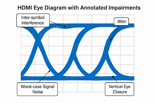
- Oscilloscopes with HDMI probe adapters (for eye diagrams)
- EDID readers to confirm display capabilities
- Protocol analyzers to decode TMDS symbols and InfoFrames
- HDMI loopback testers and pattern generators
Using Premium Certified High-Speed HDMI cables with active repeaters or equalizers is recommended for 4K60 and higher.
Why TMDS Is Still Relevant
Despite being over 20 years old, TMDS remains a resilient, low-latency, and cost-effective signaling method. Its elegant blend of transition minimization, DC balancing, and symbol encoding laid the groundwork for HDMI’s widespread success. Even as HDMI 2.1 transitions to FRL, understanding TMDS is critical for compatibility, diagnostics, and integration in mixed-environment installations where legacy and modern devices coexist.
-
DDC & EDID – The Hidden Handshake Behind HDMI Compatibility
What Is DDC and Why Is It Essential
The Display Data Channel (DDC) is a low-speed, bidirectional communication interface. The DDC interface was defined by the VESA standard. In addition, it is integrated into HDMI to support display identification, configuration, and authentication. It enables the source device (like a PC, Blu-ray player, or game console) to query the sink device (TV, monitor, AV receiver) for its supported video/audio formats using a special data structure known as EDID (Extended Display Identification Data).
“If EDID negotiation fails, the whole AV chain collapses—even if every cable is perfect.”
Without DDC, HDMI would not be “plug and play.” The DDC/EDID layer ensures that:
- The display’s capabilities (resolutions, refresh rates, color spaces, audio formats) are known to the source
- The HDCP handshake (for content protection) can take place
- Display timing can be negotiated before video transmission begins
Even though it operates at a much lower speed than TMDS, DDC is mission-critical to every HDMI connection.
DDC Electrical Layer: I²C-Based Serial Link
The DDC interface in HDMI is electrically identical to I²C, consisting of:
- SCL (Pin 15): Serial Clock Line
- SDA (Pin 16): Serial Data Line
- DDC Ground (Pin 17): Shared reference ground for noise immunity
- +5V (Pin 18): Source-supplied power for pull-up biasing (50 mA max)
These lines support standard-mode I²C at 100 kHz. However, it is slow by modern standards, but sufficient for configuration tasks.
Important Constraint:
Because HDMI uses passive wiring with resistive pull-ups on SDA and SCL, signal integrity issues (capacitance, line length, poor shielding) can corrupt EDID reads or HDCP exchanges.
EDID: What It Contains and How It Works
EDID (Extended Display Identification Data) is a structured 128-byte (or more) data block. EDID data is stored in the display’s EEPROM. It is accessible via I²C and read by the source.
EDID Contents:
| Field | Description |
| Header | 8-byte fixed pattern: 00 FF FF FF FF FF FF 00 |
| Manufacturer ID | 2-character vendor code (e.g., DEL for Dell) |
| Product Code | Identifies the display model |
| Serial Number | Optional unique ID |
| Manufacture Date | Week/year of manufacture |
| EDID Version | Usually 1.3 or 1.4 |
| Basic Display Parameters | Video input type, aspect ratio, gamma |
| Chromaticity Coordinates | Color primaries (CIE 1931) |
| Established Timings | Legacy resolutions (e.g., 640×480@60Hz) |
| Standard Timings | 8 modes defined by pixel rate/aspect |
| Detailed Timing Descriptors | 4 user-defined or standard modes |
| Monitor Name & Serial | ASCII strings, optional |
| Extension Flag | Indicates the presence of additional blocks |
| Checksum | Byte-wise XOR validation |
Modern HDMI displays often include EDID extensions:
- CEA-861 Extension Block: It adds detailed info about supported resolutions, audio formats, speaker configuration, and Vendor-Specific Data Blocks (VSDB) (HDMI 1.4/2.0 capabilities, HDR metadata).
- CTA-861-G: HDMI 2.1 additions like Dynamic HDR, ALLM (Auto Low Latency Mode), and VRR flags.
EDID Extension Blocks
Each EDID extension block is 128 bytes. EDID 1.3 supports one block. However, EDID 1.4 and beyond support multiple (Block 0: base EDID, Block 1: CEA, Block 2: CTA-HDR).
E-EDID: Extended EDID and Modern Enhancements
E-EDID (Enhanced EDID) allows up to 32 x 128-byte extension blocks. That facilitates modern HDMI requirements like:
- Multi-channel PCM and compressed audio (Dolby Digital, DTS, Atmos)
- Deep Color and wide color gamuts
- HDR formats (HDR10, Dolby Vision, HLG, Dynamic HDR)
- HDMI 2.1-specific flags (FRL support, DSC compression, eARC capability)
Data Block Types in CTA-861-G include:
- Video Data Blocks
- Audio Data Blocks
- Speaker Allocation Data Blocks
- Vendor-Specific Data Blocks (VSDB)
- HDR Static Metadata Blocks
- YCBCR 4:2:0 Video Data Blocks
- HDMI 2.1 VSDB with FRL, DSC, ALLM flags
DDC and HDCP: Key Exchange and Authentication
HDCP (High-bandwidth Digital Content Protection) uses DDC as the physical transport for exchanging:
- Device keys and capabilities
- Session keys
- Authentication status
Authentication Steps:
- DDC reads to verify HDCP capability
- Exchange of KSVs (Key Selection Vectors)
- SHA-1 hash comparison
- Encrypted key derivation
- TMDS data stream encryption begins
If DDC fails due to signal integrity, power, or timing issues, then HDCP will fail. That is leading to:
- Black screens
- Flickering
- “HDCP unauthorized” errors
DDC/EDID Troubleshooting & Emulation Techniques
Common Problems:
- Corrupt EDID: Causes resolution fallback or detection failures
- EDID mismatch: AV receivers sometimes alter EDID to enforce compatibility, breaking passthrough
- Cable capacitance: Causes DDC signal degradation with long cables or Y-splitters
- Incorrect pull-ups or floating SDA/SCL lines
Diagnostic Tools:
- EDID Readers (hardware or software)
- DDC sniffers (I²C probes or HDMI analyzers)
- HDCP analyzers for compliance testing
Advanced Use Cases:
- EDID Emulation: Used to override faulty displays or force custom timings
- EDID Editors: Tools like AW EDID Editor or Analog Way provide byte-level customization
- Display Emulators (EDID Ghosts): Devices that insert a programmable EDID between source and sink to prevent handshake issues
Why DDC and EDID Matter in HDMI Systems
DDC and EDID are often overlooked. However, both are absolutely critical to HDMI’s plug-and-play operation. They govern everything from:
- Display detection
- Supported resolutions and frame rates
- Audio format selection
- HDCP encryption
- HDR metadata exchange
Failures in this layer can prevent HDMI systems from initializing. That may cause incorrect resolution fallback or block content playback. For AV integrators, system designers, and advanced users, mastery of DDC/EDID gives you the power to engineer around compatibility limitations. The knowledge on DDC/EDI, simulates display environments, and troubleshoots stubborn HDMI problems with confidence.
-
CEC (Consumer Electronics Control) – The Hidden Bus Powering Device Interoperability
What Is HDMI CEC and Why Does It Matter
Consumer Electronics Control (CEC) is an integral but often misunderstood feature of HDMI. It enables inter-device communication and control through a dedicated single-wire bus embedded within the HDMI cable (Pin 13). Using CEC, devices like TVs, soundbars, Blu-ray players, and game consoles can send and receive low-speed control commands. It allows a single remote to orchestrate multiple devices.
CEC operates independently of the TMDS and DDC channels. CEC functions even when no video signal is active. It is part of the HDMI protocol stack. However, has its own:
- Physical layer
- Data link layer
- Protocol syntax
- Addressing mechanism
- Command set (opcodes and parameters)
- Powering off all devices with one remote (One-Touch Play)
- Controlling AV receivers or Blu-ray players via the TV remote
- Automatically switching inputs
- Triggering the system to stand by when the TV turns off
- Volume control via the TV’s remote for ARC/eARC devices
CEC Physical Layer: Electrical Characteristics
CEC uses Pin 13 on the HDMI connector, a single-wire, open-drain bus pulled up to 3.3V via a 27kΩ resistor. All connected devices share the same bus.
- Signal voltage: Logic Low = ~0V, Logic High = ~3.3V
- Line idle state: High (3.3V)
- Drivers: Open-drain (wired-AND logic)
- Speed: ~1 byte/ms → Max 400 bits/sec (very low speed)
CEC requires strong timing precision despite its low speed:
- Start bit timing
- Data bit sampling
- Acknowledgment windows
Challenge: Because CEC is single-wire, all devices must coexist on the same bus. That is making it susceptible to signal conflicts, electrical noise, and firmware bugs.
CEC Logical Architecture: Layers and Roles
CEC is structured across several layers:
| Layer | Role |
| Physical | Single-wire serial communication (Pin 13) |
| Data Link | Message framing, addressing, and arbitration |
| Protocol | Commands (opcodes), parameter sets |
| Application | Device-specific interpretation of control messages |
Each HDMI device implements a logical address. The logical address itself defines its role in the HDMI-CEC network.
| Address | Device Type |
| 0 | TV |
| 1 | Recorder 1 |
| 2 | Recorder 2 |
| 3 | Tuner 1 |
| 4 | Playback Device 1 |
| 5 | Audio System |
| 6–14 | Additional devices |
| 15 | Broadcast (unaddressed) |
Each physical HDMI port (TV Port 1, Port 2) maps to a physical address like 1.0.0.0, 2.0.0.0, etc., assigned during topology discovery via DDC.
CEC Message Structure and Timing
CEC messages are frame-based and consist of:
| Field | Description |
| Header | Initiator (source) + destination (target) logical address |
| Opcode | Command identifier (e.g., 0x44 = User Control Pressed) |
| Operands | Optional parameters (e.g., Volume Up) |
| EOM + ACK | End-of-message bit and device acknowledgment |
Example:
44:7E:41
– 44 = User Control Pressed
– 7E = Playback Device 2 to Audio System
– 41 = Volume Up
CEC supports broadcast messaging using logical address 0x0F (unregistered). It is often used for One-Touch Play or System Standby.
5.4 CEC Command Categories (Opcodes)
CEC defines over 100 opcodes in the HDMI 1.4 and 2.1 specifications. They fall into key categories:
Playback and Power Control
- 0x04: Image View On (TV turns on + switches input)
- 0x0D: Standby (turns off all devices)
- 0x82: Active Source (source requests control of TV input)
System Information and Topology
- 0x9F: Get CEC Version
- 0x83: Give Physical Address
- 0x8F: Set Menu Language
User Control Commands
- 0x44: User Control Pressed
- 0x45: User Control Released
- Operands include Play, Pause, Stop, Volume Up, and Mute
Audio Control (especially ARC/eARC devices)
- 0x70: System Audio Mode Request
- 0x72: Set System Audio Mode
- 0x7D: Audio Rate Control
5.5 ARC and CEC Integration
CEC is used to control the Audio Return Channel (ARC) state. For example:
- When a TV detects an ARC-capable AV receiver, it sends a System Audio Control request (0x70) to enable audio forwarding.
- Volume control over CEC allows the TV’s remote to adjust the volume of the soundbar or AV receiver via User Control Commands (0x44, 0x41).
eARC (HDMI 2.1) replaces some CEC control with a dedicated eARC Data Channel. However, CEC is still used for system-wide standby and routing commands.
CEC Compatibility Challenges and Workarounds
Despite its powerful capabilities, CEC is notoriously buggy due to:
- Non-standard implementation across manufacturers
- Poor or conflicting device firmware
- Signal conflicts on shared CEC bus
- Over-aggressive or passive CEC logic
Common Problems:
- The TV turns on or off other devices unexpectedly
- HDMI input switches without user action
- Devices don’t respond to CEC commands
- CEC stops working after firmware updates
Troubleshooting Tools:
- CEC sniffers/analyzers (Pulse-Eight USB-CEC Adapter)
- HDMI switchers with CEC isolation
- EDID emulators to prevent undesired CEC triggers
- Disabling CEC per device or per port when needed
Many TVs allow CEC to be turned off under brand names like Anynet+ (Samsung), Bravia Sync (Sony), SimpLink (LG), or Viera Link (Panasonic).
CEC Enables Seamless Control—When It Works
HDMI CEC is a powerful but delicate part of the HDMI ecosystem. It facilitates true interoperability between AV components. It is giving users simplified control through a unified command interface. But its success hinges on precise electrical behavior, vendor compliance, and correct system topology.
For advanced users, integrators, and developers, understanding how CEC works at the electrical, protocol, and command level unlocks the ability to:
- Debug AV automation issues
- Implement custom CEC logic via Raspberry Pi or microcontrollers
- Suppress or reroute misbehaving control traffic
-
ARC, eARC, and HEAC Explained – The Return and Data Channels in HDMI
HDMI is widely known for sending high-fidelity video and audio from a source to a display. Besides, more recent HDMI versions also support upstream transmission. That is most notably Audio from the TV back to an AV receiver or soundbar, and in some cases, Ethernet data. These capabilities are enabled through ARC (Audio Return Channel), eARC (Enhanced ARC), and HEAC (HDMI Ethernet and Audio Control).
Understanding how these return channels and auxiliary channels work helps you to understand both electrically and logically. In addition, it unlocks their full potential in AV integration, troubleshooting, and bandwidth optimization.
What Is ARC (Audio Return Channel)?
Introduced in HDMI 1.4, ARC allows a TV to send audio upstream to a connected HDMI source device like a soundbar or AV receiver. It is possible over the same HDMI cable used for video. This is eliminating the need for a separate S/PDIF (TOSLINK) optical cable. This method simplifies system design.
Use Case:
When you watch content using an app built into your smart TV (Netflix, YouTube), ARC enables the TV to send that audio back to your receiver for decoding and amplification.
How It Works (Signaling Layer):
- ARC repurposes the TMDS clock channel (Pins 10 and 11) to transmit audio from sink to source.
- ARC is half-duplex: TMDS audio cannot be transmitted from both ends at once.
- The CEC protocol (Pin 13) is used to negotiate and control ARC activation.
ARC Audio Capabilities:
| Format | Support |
| PCM (2.0) | yes |
| Dolby Digital (5.1) | yes |
| DTS Digital Surround | optional |
| Dolby Digital Plus | limited |
| Dolby Atmos (via DD+) | compressed only |
| Dolby TrueHD / DTS-HD MA | not supported |
Limitations of ARC:
- Limited bandwidth (~1 Mbps)
- Audio format support is constrained
- Susceptible to handshake issues
- Requires CEC to be enabled and functioning
What Is eARC (Enhanced Audio Return Channel)?
With the emergence of object-based and high-bitrate audio formats (Dolby Atmos, DTS:X, TrueHD, DTS-HD MA), ARC’s limitations became a bottleneck. HDMI 2.1 introduced eARC. 2.1 comes with a major overhaul of ARC with dedicated data paths, wider bandwidth, and CEC independence.
eARC: Architecture and Electrical Signaling
eARC introduces a dedicated, full-duplex differential pair that replaces the legacy ARC use of TMDS clock pins.
| Signal | Pins Used | Mode |
| eARC TX+/TX− | Pin 2 and Pin 3 | Differential data (from TV to AVR) |
| eARC RX+/RX− | Pin 14 and Pin 19 | Control and status feedback |
Unlike ARC, eARC does not depend on CEC for its operation. It uses its own eARC Data Channel (eARC DC) for discovery, capability exchange, and health monitoring.
eARC Protocol Stack:
- Control Channel: Handles capability exchange, latency reporting, and audio mode switching
- Transport Layer: Transmits uncompressed audio using IEC 60958 (LPCM) and IEC 61937 (compressed formats)
- FEC & Framing: Adds robust error correction and timing synchronization
eARC Audio Capabilities:
eARC provides up to 37 Mbps of dedicated bandwidth, supporting:
| Audio Format | eARC Support |
| PCM (up to 8ch, 192 kHz, 24-bit) | Yes |
| Dolby Digital / DTS | Yes |
| Dolby Digital Plus (DD+) | Yes |
| Dolby Atmos (via DD+ or TrueHD) | Yes |
| Dolby TrueHD (lossless) | Yes |
| DTS-HD Master Audio | Yes |
| DTS:X | Yes |
| AAC / MPEG audio | Yes (if source-dependent) |
eARC enables full lossless object-based audio. It is a game-changer for home theaters. It is eliminating the need for Blu-ray player passthrough.
eARC vs ARC: Technical Comparison
| Feature | ARC | eARC |
| Introduced in | HDMI 1.4 | HDMI 2.1 |
| Bandwidth | ~1 Mbps | ~37 Mbps |
| Cable Requirement | High-Speed HDMI | Ultra High-Speed HDMI (for max stability) |
| Audio Formats | PCM 2.0, Dolby Digital, DTS | All ARC formats + TrueHD, DTS-HD MA, Atmos, DTS:X |
| Control Signaling | CEC required | eARC Data Channel (CEC-independent) |
| Error Correction | None | FEC-enabled |
| Latency Handling | Limited | Latency reporting & sync optimization |
Important Considerations:
- eARC requires both devices to support HDMI 2.1 eARC natively.
- If one device only supports ARC, then the link will fall back to ARC automatically.
- Some HDMI 2.0 TVs support eARC via firmware. However, this varies according to the brand.
What Is HEAC (HDMI Ethernet and Audio Control)?
HEAC is a lesser-known feature introduced in HDMI 1.4. It is aimed at combining ARC and Ethernet over HDMI.
HEAC Capabilities:
- Ethernet @ 100 Mbps between HDMI devices
- Audio Return Channel (ARC) over the same pins
- Enables IP-based AV networking over HDMI
Electrical Implementation:
| Signal | Pins Used |
| HEAC+ | Pin 14 |
| HEAC− | Pin 19 |
HEAC reuses ARC/eARC control pins and requires HEAC-compatible HDMI ports and Category 2 (High-Speed) cables.
Industry Adoption:
HEAC saw little to no real-world implementation due to:
- Lack of Ethernet switching integration in AV devices
- Incompatibility with existing HDMI chipsets
- Better alternatives (Wi-Fi, HDMI-over-IP extenders)
Real-World eARC System Design Best Practices
To take full advantage of eARC:
Cable Selection:
- Use Ultra High-Speed HDMI cables (certified for HDMI 2.1)
- Avoid HDMI extenders or switches unless eARC-certified
System Validation:
- Ensure both devices support native eARC (not just ARC)
- Test with high-bitrate source content (TrueHD Atmos)
- Use TV settings to enable PCM or Bitstream over eARC
Device Setup:
- Disable ARC auto fallback if possible
- Set the TV and AV Receiver to “eARC Preferred” or “Auto”
Diagnostic Tools:
- Use eARC sniffers or HDMI analyzers (Murideo, Astro Design)
- Check for EDID extensions that list eARC support
- Monitor HDMI Vendor-Specific InfoFrames (VSIF) for eARC flags
ARC, eARC, and HEAC—Backward, Forward, and (Sometimes) Sideways
ARC and eARC represent the evolution of upstream audio transmission in HDMI. eARC offers the bandwidth, reliability, and fidelity required for next-gen AV formats. HEAC, although conceptually innovative, remains a niche implementation.
For integrators, audio engineers, and enthusiasts, understanding the differences between ARC and eARC, along with signal wiring, protocol roles, and cable dependencies, is crucial to designing future-ready AV systems that deliver immersive sound without compromise.
-
Fixed Rate Link (FRL) – The Successor to TMDS in HDMI 2.1
The resolutions, frame rates, and color depths have increased tremendously. Therefore, the traditional HDMI transmission method, Transition Minimized Differential Signaling (TMDS), has reached its practical limits.
HDMI 2.1 bandwidth requirements:
To meet the bandwidth demands of formats like 4K120, 8K60, HDR with 12-bit color, and Display Stream Compression (DSC), the HDMI 2.1 specification introduces a radically upgraded transport protocol: Fixed Rate Link (FRL).
“FRL is the biggest leap in HDMI transmission since TMDS. It’s not just about bandwidth—it’s about error correction, future-proofing, and AV integrity.”
— Silicon Image Whitepaper, 2019
FRL replaces TMDS in high-bandwidth modes. FRL offers not only significantly more capacity but also improved robustness, error correction, and training mechanisms. It is ushering HDMI into the ultra-high-speed era.
Why TMDS Was Not Enough
TMDS Limitations in HDMI 2.0:
| Factor | TMDS (HDMI 2.0) |
| Max Bandwidth | 18 Gbps (3 × 6.0 Gbps) |
| Encoding Overhead | 8b/10b (25%) |
| Effective Throughput | ~14.4 Gbps |
| Max Resolution | 4K60 4:4:4 at 8-bit |
| HDR Overhead | Further reduces usable bandwidth |
| Cable Length Constraints | Severe at 18 Gbps |
To push beyond 4K60 without quality compromises, HDMI 2.1 replaces TMDS with FRL. FRL is capable of up to 48 Gbps total bandwidth with lower overhead and advanced error correction.
FRL Architecture and Design Philosophy
FRL = Packetized Data + Forward Error Correction + Scalable Lanes
Unlike TMDS’s continuous stream encoding, FRL is a packet-based, burst-mode protocol designed with less overhead and more resiliency.
Key Features of FRL:
| Feature | Description |
| Link Speed | 3 to 12 Gbps per lane |
| Lanes Used | 3 or 4 |
| Encoding | 16b/18b (11.1% overhead vs 25% for TMDS) |
| Total Bandwidth | Up to 48 Gbps (4 lanes × 12 Gbps) |
| Error Correction | Yes, via Reed-Solomon-based FEC |
| Training Protocol | Link Training with Feedback (LTF) |
| Supported by | HDMI 2.1+ devices only |
| Backward Compatible? | Yes (TMDS fallback) |
FRL Link Rates and Modes
HDMI 2.1 defines eight FRL link modes. Each FRL link is designated as FRLx:
| FRL Mode | Lanes Used | Lane Rate (Gbps) | Total Bandwidth | Example Use Case |
| FRL3 | 3 | 3 Gbps | 9 Gbps | 1080p240 SDR |
| FRL4 | 4 | 3 Gbps | 12 Gbps | 1440p144 SDR |
| FRL5 | 4 | 6 Gbps | 24 Gbps | 4K60 4:2:0 10-bit |
| FRL6 | 4 | 8 Gbps | 32 Gbps | 4K60 4:4:4 10-bit |
| FRL7 | 4 | 10 Gbps | 40 Gbps | 4K120 4:4:4 or 8K30 |
| FRL8 | 4 | 12 Gbps | 48 Gbps | 8K60 4:4:4 HDR |
| DSC Modes | 3–4 | Any | Varies | 8K120 with Display Stream Compression |
Note on Effective Bandwidth:
Due to 16b/18b encoding, the actual data payload is about 88.8% of raw bandwidth.
FRL Training and Negotiation Process
FRL is not always active. Devices begin in TMDS mode and only switch to FRL after successful negotiation via FRL Link Training over the Display Data Channel (DDC).
Training Process Overview:
- EDID Parsing: Sink advertises FRL capability and supported FRL rates via EDID and SCDC.
- Source Initiates LTF (Link Training with Feedback): Uses auxiliary channel to start training.
- Lane Equalization: The Source sends training patterns. Sink measures signal integrity.
- Sink Feedback: If training fails, then the rate is reduced or TMDS is used.
- FRL Enabled: Upon success, FRL mode begins, and high-bandwidth data is transmitted.
Poor HDMI cables or non-certified devices often fail FRL negotiation. It is causing a fallback to lower resolutions or no signal.
FRL Packet Structure and Protocol Layering
FRL transmits packets, not continuous symbol streams. The structure includes:
- FRL Data Packets: Carry video, audio, metadata, and InfoFrames
- Link Layer Frames: Include headers, payloads, CRCs, and Error correction codes
- FEC Layer: Adds robust Reed-Solomon parity to tolerate bit errors over long distances
Advantages of Packetized Architecture:
- Better integration with digital video processors
- Reduced jitter and EMI vs TMDS
- Easier support for variable frame rate (VRR) and ALLM
- Improved performance with Display Stream Compression (DSC)
Display Stream Compression (DSC) in FRL
FRL supports DSC 1.2a. It is a visually lossless compression standard from VESA. It is used when raw FRL bandwidth is insufficient.
| Format | Raw Bandwidth Required | FRL + DSC |
| 8K60 4:4:4 10-bit | ~72 Gbps | ~24 Gbps w/ DSC |
| 4K120 4:4:4 10-bit | ~48 Gbps | ~18–24 Gbps w/ DSC |
DSC enables:
- 8K120, 10K60, and other extreme modes
- Minimal latency (~1 line delay)
- 2:1 to 3:1 Compression ratios
- 4:2:2 and 4:4:4 Chroma modes
- HDR10, Dolby Vision, and HLG compatibility
TMDS vs FRL: A Technical Comparison
| Feature | TMDS | FRL |
| Introduced In | HDMI 1.0 | HDMI 2.1 |
| Max Bandwidth | 18 Gbps | 48 Gbps |
| Encoding Overhead | 8b/10b (25%) | 16b/18b (11.1%) |
| Transport Mode | Serial, Unpacketized | Packet-based |
| Error Correction | None | Yes, FEC + CRC |
| Training | None | Required via LTF |
| Backward Compatible | Native | Fallback to TMDS |
| Use Case | 1080p, 4K60 | 4K120, 8K60, DSC modes |
Practical Implementation Challenges and Solutions
Common Issues with FRL:
- Cable limitations: Poor-quality HDMI cables fail at 10 or 12 Gbps lane rates
- Signal crosstalk: High FRL lanes require superior PCB and connector design
- FRL training failures: Cause no signal or TMDS fallback
- EDID errors: Sink fails to report correct FRL capability
Best Practices:
- Use Ultra High-Speed HDMI Certified Cables (48 Gbps)
- Avoid passive extenders, splitters, or switches unless FRL-certified
- Check for FRL rates in EDID or SCDC registers
- Use HDMI analyzers to confirm successful FRL negotiation
- Ensure firmware on both source and sink supports FRL training and DSC if needed
FRL Is the Future of HDMI High-Speed Transmission
Fixed Rate Link (FRL) redefines how HDMI transports data. FRL is replacing TMDS with a flexible, scalable, error-tolerant system that enables 4K120, 8K60, 12-bit HDR, and DSC compression. It provides the bandwidth needed for modern and future AV formats without sacrificing compatibility.
For AV professionals, integrators, and engineers, mastering FRL means understanding:
- The packetized nature of the link
- The importance of training and negotiation
- The role of cables and signal integrity
- The interplay with DSC, ALLM, VRR, and HDR metadata
-
Auxiliary and InfoFrame Channels – The Metadata Highways of HDMI
HDMI is more than just pixels and audio. It is also a sophisticated metadata delivery system. From video timing and colorimetry to HDR signaling, content type, and audio layout, HDMI uses specialized InfoFrame packets and auxiliary channels to communicate critical instructions to the display and connected devices.
These invisible data streams are vital for ensuring proper rendering of images, correct color mapping, and seamless interoperability across diverse HDMI sources and sinks.
What Are InfoFrames in HDMI?
InfoFrames are structured metadata packets embedded within the HDMI signal stream. It is typically transmitted during the vertical blanking interval (VBI). They do not consume additional bandwidth and are not part of the main video/audio payload. However, they are essential for instructing the display on how to interpret the content.
Each InfoFrame has:
- Header (3 bytes): Type, Version, Length
- Payload (variable): Parameter-specific data
- Checksum (1 byte): Validation
HDMI defines several InfoFrame types, most notably:
- AVI InfoFrame – Video format & color metadata
- Audio InfoFrame – Audio stream configuration
- Vendor-Specific InfoFrame (VSIF) – HDMI-specific or Dolby Vision/HDR extensions
- HDR Static Metadata InfoFrame (per CTA-861.3)
AVI InfoFrame: Defining Video Parameters
The Auxiliary Video Information (AVI) InfoFrame, Type 0x82, is fundamental to how the sink interprets incoming video. It tells the display what kind of signal is coming and how to render it.
Key Fields in AVI InfoFrame:
| Field | Description |
| Video Format Identification Code (VIC) | Matches to standard timings (16 = 1920x1080p@60) |
| Color Space | RGB, YCbCr 4:4:4, 4:2:2, 4:2:0 |
| Colorimetry | ITU-R BT.601, BT.709, BT.2020 |
| Picture Aspect Ratio | 4:3, 16:9 |
| Active Format Aspect Ratio (AFAR) | For letterboxing/pillarboxing |
| Scan Info | Interlaced or Progressive |
| Quantization Range | Limited (16–235) or Full (0–255) |
| Video Identification | Info for Source/Display alignment |
Why It Matters:
Incorrect or missing AVI InfoFrames can cause:
- Washed-out or crushed blacks (color range mismatch)
- Wrong aspect ratio (image stretch or crop)
- Color inaccuracies (improper gamut mapping)
Audio InfoFrame: Audio Channel Layout and Format
The Audio InfoFrame (Type 0x84) delivers metadata about the active audio stream to the sink. That is ensuring correct speaker assignment, decoding mode, and synchronization.
Key Audio InfoFrame Fields:
| Field | Description |
| Channel Count | 2–8 (for LPCM); extended via E-EDID |
| Sample Frequency | 32/44.1/48/88.2/96/176.4/192 kHz |
| Sample Size | 16/20/24 bits |
| Coding Type | LPCM, AC-3, DTS, DTS-HD, Dolby MAT, etc. |
| Speaker Allocation | FL, FR, C, LFE, SL, SR, RL, RR, etc. |
HDMI 2.1 with eARC allows up to 32 audio channels. Audio InfoFrames can signal complex layouts like Atmos bed channels and height speakers.
Vendor-Specific InfoFrame (VSIF): Extension Metadata Container
The Vendor-Specific InfoFrame (Type 0x81) is a flexible container used by HDMI and third-party standards (like Dolby, HDMI Forum) to transmit additional data not covered by AVI or Audio InfoFrames.
Use Cases:
- Signaling HDMI version capabilities (FRL, DSC, VRR)
- Identifying Dolby Vision metadata presence
- Announcing 3D video formats (Frame Packing, Side-by-Side)
- Enabling ALLM (Auto Low Latency Mode)
Vendor Block Examples:
| Vendor | VSIF Contents |
| HDMI Forum | HDMI 2.1 FRL status, DSC flag, VRR min/max rates |
| Dolby | Dolby Vision mode, L5 metadata payload format |
| CEA (CTA-861-H) | 3D structure indicator |
| AMD/NVIDIA | FreeSync or G-Sync VRR extensions |
VSIFs are dynamic: They can change per frame to reflect content switching (from SDR to HDR).
HDR Static Metadata InfoFrame (HDR InfoFrame)
Defined by CTA-861.3, the HDR Static Metadata InfoFrame (Type 0x87) provides PQ (Perceptual Quantizer) or HLG (Hybrid Log-Gamma) signaling information, so the display can:
- Apply proper Electro-Optical Transfer Function (EOTF)
- Adjust tone mapping
- Enable local dimming or wide color gamut (WCG) modes
HDR Static Metadata Structure:
| Field | Description |
| EOTF Type | 0: SDR, 1: PQ (HDR10), 2: HLG |
| Metadata Descriptor ID | Identifies the static metadata format |
| Max Display Luminance | 1000 nits |
| Max Content Light Level (MaxCLL) | Peak brightness of mastered content |
| Max Frame-Average Light Level (MaxFALL) | Frame-wise brightness envelope |
These fields are critical for proper tone-mapping and HDR rendering. That is especially on displays that support dynamic HDR (Dolby Vision, HDR10+), where base HDR InfoFrame still anchors fallback behavior.
Dynamic Metadata & Auxiliary InfoFrames
HDR10 uses static metadata. However, some modern formats like HDR10+ and Dolby Vision require frame-by-frame or scene-by-scene metadata updates. These are transmitted via:
- Dynamic HDR InfoFrames
- VSIF extensions (Dolby L5 format)
- Auxiliary InfoPackets (if available in the pipeline)
This dynamic data can include:
- Scene luminance ranges
- Real-time mastering data
- Tone-mapping curves
- Ambient light adaptation parameters
Frame-sequenced InfoFrames are embedded before or after each vertical blanking interval (VSync) to ensure timing alignment with video content.
How Displays and Sources Parse InfoFrames
HDMI sinks (TVs, monitors, AVRs) must parse InfoFrames in real-time using:
- SCDC (Status and Control Data Channel) for HDMI 2.0/2.1 streams
- Auxiliary hardware FIFOs in HDMI RX ICs
- Microcontroller firmware routines for field-based changes
Modern SoCs use InfoFrame parsers to:
- Trigger color space conversion (YUV → RGB)
- Activate HDR processing
- Enable audio decoders (Dolby Atmos via MAT container)
- Auto-switch game mode (ALLM)
Troubleshooting InfoFrame Issues
Symptoms of InfoFrame Failures:
- Washed-out or oversaturated color (wrong Colorimetry or quantization)
- Black screens or dropped frames (incompatible HDR metadata)
- Audio loss (incorrect channel map or format mismatch)
- Display stuck in SDR/HDR mode incorrectly
Tools to Inspect InfoFrames:
- HDMI protocol analyzers (Astro, Quantum Data, Murideo)
- SCDC/EDID dumpers to confirm advertised capabilities
- VSIF sniffers or deep HDMI firmware logs (in professional tools)
- LogiCORE HDMI RX IP (for FPGA HDMI devkits)
Advanced Use: Developers often simulate InfoFrames to test display behavior using custom generators or PC-based HDMI emulation tools.
InfoFrames and Metadata—The Silent Pillars of HDMI Intelligence
TMDS and FRL carry raw video/audio data. However, HDMI InfoFrames ensure that every frame is displayed and decoded correctly. From color space and resolution to HDR and audio layout, InfoFrames act as the semantic glue between devices.
Mastering these auxiliary channels is critical for:
- AV integrators fine-tuning signal chains
- Engineers building HDMI TX/RX systems
- Developers implementing adaptive display logic
- Troubleshooting mysterious display or audio errors
HDMI continues to evolve with dynamic HDR, higher frame rates, and interactive metadata. Therefore, InfoFrames will only become more vital in delivering immersive and accurate AV experiences.
-
EDID & InfoFrame Interplay – Negotiation and Real-Time Signaling in HDMI
In the HDMI communication stack, EDID (Extended Display Identification Data) and InfoFrames serve as complements. However, they fundamentally play different roles: capability discovery and runtime configuration. EDID helps the source identify what the sink can support. InfoFrames inform the sink what is being sent right now.
Understanding the intricate interplay between EDID and InfoFrames is critical for AV engineers, display manufacturers, content creators, and integrators. Understanding it can deliver optimal visual and auditory fidelity while maintaining compatibility across devices.
EDID: The Display’s Capability Manifest
EDID is a metadata structure stored in the sink (TV, monitor, projector) and accessed by the source via the Display Data Channel (DDC). It is a two-wire I²C bus (Pins 15 and 16). It is read during HDMI Hotplug detection or upon manual refresh.
Core Components of EDID:
| Block | Description |
| Header | EDID signature (00 FF FF FF FF FF FF 00) |
| Basic Display Parameters | Screen size, gamma, features |
| Timing Descriptors | Resolutions, refresh rates |
| CEA Extension Block | HDMI-specific additions |
| Audio Block | Supported codecs & speaker layouts |
| Video Data Block | VIC codes for display modes |
| Colorimetry Block | BT.709, BT.2020, sRGB, etc. |
| HDR Static Metadata Block | EOTF, luminance, MaxCLL/MaxFALL |
| Vendor-Specific Block | HDMI Forum, Dolby, HDMI 2.1, etc. |
EDID is static: It reflects supported capabilities, not active usage.
InfoFrames: Real-Time State Descriptors
EDID defines the “contract” of what the sink can handle. InfoFrames are dynamic runtime descriptors sent by the source. These packets tell the sink how to interpret the current video/audio signal, not what it could be.
Key InfoFrame Functions:
- Instruct the display to use YUV 4:2:2 instead of RGB
- Signal BT.2020 color gamut in HDR video
- Notify AVR of Dolby Atmos MAT audio
- Trigger ALLM or VRR modes
- Align tone mapping via MaxCLL/MaxFALL values
InfoFrames are regenerated on the fly when a new resolution, HDR mode, or content type is detected.
Interplay Flow: How EDID and InfoFrames Work Together
Negotiation → Transmission → Rendering Pipeline
Sink (TV/AVR) Source (GPU, Blu-ray) Sink
[EDID] ←──────────── DDC/I²C ──────────────→ [Parses InfoFrames]
(Reports capabilities) (Sends InfoFrames per frame)
- EDID Readout:
- Source reads EDID and determines valid display modes (VICs), audio formats, colorimetry, and HDR support.
- Mode Selection:
- Source chooses optimal output (4K60 HDR10 with BT.2020) based on content and user settings.
- InfoFrame Generation:
- Source encodes video/audio stream and embeds matching InfoFrames for:
- AVI InfoFrame (Video Identification Code, color space)
- HDR InfoFrame (Static Metadata)
- VSIF (Dynamic HDR, Dolby Vision, FRL/DSC flags)
- Source encodes video/audio stream and embeds matching InfoFrames for:
- Sink Response:
- Display parses incoming InfoFrames and adjusts the rendering pipeline accordingly (EOTF, scaling, gamut mapping).
Examples of EDID-InfoFrame Synchronization
Example 1: HDR Video Playback
- EDID Block: Indicates support for EOTF = PQ (HDR10) and BT.2020 colorimetry.
- Source Decision: Outputs HDR10 stream in 4K60 with BT.2020 and MaxCLL = 1000 nits.
- AVI InfoFrame: Sets Colorimetry = BT.2020, RGB Limited Range
- HDR InfoFrame: EOTF = 1 (PQ), MaxCLL = 1000, MaxFALL = 300
Example 2: Dolby Atmos Audio
- EDID Audio Block: Supports MAT format with 8 channels and object-based decoding.
- Source Decision: Outputs Dolby Atmos over TrueHD (bitstream)
- Audio InfoFrame: Sets coding type = Dolby MAT, 8 channels
- VSIF: Signals Dolby Vendor Block with L5 dynamic metadata (if Dolby Vision is active)
HDMI Version Dependencies and Pitfalls
Common Pitfalls in EDID–InfoFrame Coordination:
| Problem | Cause |
| HDR not activating | Sink’s EDID lacks HDR Static Metadata Block |
| Washed out colors | Quantization Range mismatch between EDID and AVI InfoFrame |
| Dolby Vision not detected | Missing VSIF or incorrect Vendor ID |
| Audio dropouts | Source misreads EDID audio block or wrong channel count in InfoFrame |
| VRR not engaging | EDID lacks VRR capability declaration, or VSIF was not sent properly |
Debugging Tools:
- EDID Viewers: DDC/CI tools, AVLab TPG, MonInfo, HDMI analyzers
- InfoFrame Inspectors: Murideo SIX-G, Astro HDMI analyzers
- Protocol Loggers: With SCDC/CEC + frame-level InfoFrame tracking
eARC-Specific Interactions
With eARC, the audio discovery model shifts from EDID-based to eARC capability exchange. However, InfoFrames remain critical for:
- Specifying channel layout
- Triggering System Audio Control
- Reporting latency and lip-sync metadata
Dynamic audio InfoFrames may adjust based on playback format (switching from stereo music to 7.1 surround film).
InfoFrame Redundancy and Refresh Cycles
- HDMI mandates that InfoFrames be sent at least once every 2 video frames
- They are transmitted during vertical blanking periods
- Certain InfoFrames (like HDR Static Metadata) must persist even if the content is unchanged
Dropped or corrupted InfoFrames can cause:
- Frame flicker
- Tone mapping glitches
- Audio misrouting or muting
EDID and InfoFrames—Negotiation vs Instruction
In HDMI’s architecture, EDID defines what is possible, while InfoFrames instruct the system on what is active. Together, they form a negotiation-execution loop that ensures content fidelity, compatibility, and precision rendering.
| Element | Role | Transported By | Timed |
| EDID | Capability Declaration | DDC (I²C) | One-time (hotplug) |
| InfoFrames | Active Signal Metadata | TMDS or FRL | Continuous |
Mastering EDID and InfoFrame interplay enables:
- Custom EDID crafting for compatibility
- Real-time video debugging
- Color calibration accuracy
- Advanced AV automation and troubleshooting
-
HDMI Compliance Testing & Debugging Techniques
HDMI is evolving from a basic AV interface into a complex multi-protocol transport layer (supporting TMDS, FRL, eARC, DSC, CEC, HDCP, and more). Its Compliance testing and debugging are critical in ensuring interoperability, signal integrity, and end-user reliability. Mastering HDMI debugging and compliance validation is essential for delivering HDMI-enabled devices that “work” in real-world installations.
What is HDMI Compliance Testing?
HDMI compliance testing is a structured set of physical layer, protocol, and interoperability checks mandated by HDMI Licensing Administrator, Inc. (HDMI LA) for any product claiming HDMI compatibility.
Goal: Ensure devices behave according to the HDMI specification so they interoperate flawlessly with others.
HDMI Testing Covers:
| Layer | Focus |
| Electrical (PHY) | Signal swing, rise/fall times, impedance, jitter |
| Protocol | TMDS/FRL behavior, InfoFrames, timing accuracy |
| Control Plane | CEC, EDID handling, SCDC, eARC discovery |
| Interoperability | Works across brands and HDMI versions |
| Security | HDCP 1.4 / 2.3 authentication flow |
| CTS | HDMI Compliance Test Specification dictates official test procedures |
Key HDMI Testing Categories
- Physical Layer Testing (PHY Tests)
Uses HDMI PHY analyzers to validate:
- TMDS voltage swing (400–600 mV)
- Eye pattern masks
- Jitter tolerance at 3/6/12 Gbps (TMDS/FRL)
- Intra-pair skew and crosstalk
- Cable equalization response
Tools: Keysight DSOXHDMI, Tektronix HDMI PHY Compliance Test Suite
- Protocol & Packet-Level Testing
Tests low-level behavior:
- TMDS encoding and decoding accuracy
- FRL link training (LTF) transitions
- Correct AVI, Audio, VSIF, HDR InfoFrames
- CEA-861 timings and frame structures
Tools: Quantum Data 980B, Teledyne LeCroy quantum analyzers
- EDID & SCDC Verification
Checks:
- Correct parsing of EDID extension blocks
- Accurate transmission of video/audio capabilities
- Real-time SCDC register polling (especially for FRL)
- eARC capability exchange validation (if HDMI 2.1)
Tools: Murideo 6G, 7G signal generators; ASTRO VA-1845
- HDCP Authentication Testing
Ensures correct handling of:
- HDCP 1.4 handshake (TMDS)
- HDCP 2.3 key exchange (FRL/eARC)
- Revocation list compliance
- Locality and repeaters
Tools: Simplay HDCP Test Bench, HDCP Analyzer, Tektronix DPOJET
- CEC Compliance & Traffic Analysis
CEC tests focus on:
- Logical address assignment
- Message integrity and retries
- Broadcast vs direct addressing
- Low-speed signal timing on Pin 13
Tools: Pulse-Eight CEC USB Adapter, LeCroy Protocol Analyzer, Quantum 980 CEC Viewer
- eARC and ARC Debugging
eARC requires testing for:
- Discovery protocol (eARC DC)
- Channel bandwidth negotiation
- PCM and MAT audio transmission
- Interoperability with legacy ARC
Tools: MSolutions MS-TestPro HDMI, Quantum 980B (eARC module), Astro Design HDMI Analyzer
HDMI Debugging Methodology: From Problem to Resolution
Common Symptoms and Debug Tactics:
| Issue | Possible Cause | Debugging Technique |
| No Signal / Black Screen | Failed FRL training, EDID mismatch | EDID viewer, FRL training log, scope |
| Incorrect Colors | Bad colorimetry InfoFrame, quant range mismatch | InfoFrame decoder, video test generator |
| Audio Dropouts | eARC fallback, EDID audio block missing | eARC analyzer, MAT vs LPCM packet check |
| HDCP Failures | Revoked keys, version mismatch | HDCP handshake logger, DDC bus monitor |
| VRR Not Working | VSIF error, sink does not advertise VRR | EDID block check, VSIF inspection |
| CEC Commands Ignored | Bad address assignment, line timing | CEC sniffer, oscilloscope on Pin 13 |
Key Tools & Equipment Used in HDMI Compliance & Debugging
| Tool Category | Examples | Function |
| Signal Generators | Murideo 7G, Astro VG-879 | Emulate sources and push known patterns |
| Analyzers | Quantum Data 980B, LeCroy | Capture, decode, and validate HDMI streams |
| Oscilloscopes | Tektronix MSO, Keysight | Physical layer inspection (eye diagram) |
| EDID/SCDC Readers | HDMI Doctor, Extron EDID Manager | Extract and inspect EDID/SCDC data |
| CEC Debuggers | Pulse-Eight, Cypress USB-CEC | CEC packet monitoring and triggering |
| HDCP Testers | SimplayHD, HDCPX | Validate handshake timing and encryption |
| Compliance Testers | HDMI ATC Labs, Certifiably HDMI | Full HDMI certification validation |
| eARC Tools | MS-TestPro, Murideo 8K Signal Analyzer | Validate enhanced audio return flows |
ProDigitalWeb Tip: Combine protocol-level analyzers with waveform-level scopes to identify both logical and physical root causes.
HDMI Compliance Testing Process (Official)
For certification through HDMI LA:
- Pre-Compliance Testing (in-house or via labs)
- HDMI ATC Submission (Authorized Testing Centers)
- CTS (Compliance Test Specification) Execution
- Electrical Tests
- Protocol Tests
- HDCP Validation
- CEC Interoperability
- Log Submission
- Certification & Licensing
Troubleshooting Real-World Installations
Field Debug Best Practices:
- Use HDMI extenders and splitters only if EDID passthrough and HDCP compatibility are documented.
- Always test cable quality (especially at 48 Gbps) with certified tools.
- Monitor hotplug and power sequencing. Sometimes, incorrect timing causes random failures.
- Enable InfoFrame logging during playback to catch unexpected metadata loss.
- Use test patterns (color ramps, chroma sub-sampling grids) to detect decode errors.
Best Practices for HDMI Product Development
- Simulate edge-case EDIDs (minimal audio, SDR-only).
- Validate InfoFrame behavior under resolution switches.
- Ensure fallback to TMDS and ARC if FRL or eARC fails.
- Stress-test CEC with long command chains and retries.
- Maintain firmware logging and OTA patch capability for post-deployment debugging.
HDMI Compliance is an Engineering Discipline and Diagnostic Art
Compliance testing is not only a checkbox for certification. It is a discipline that ensures signal fidelity, user satisfaction, and global interoperability. With HDMI 2.1 bringing new levels of complexity, the ability to test and debug across all layers—electrical, protocol, and behavioral—is now mission-critical.
For professionals working in AV product development, integration, or broadcast infrastructure, investing in pro-grade test equipment and building strong HDMI domain knowledge is crucial to eliminating “mystery bugs” and delivering premium-quality devices.
-
Hot Plug Detect (HPD) & Utility Channels — The Hidden Orchestrators of HDMI Handshake and Signaling
Normally, TMDS, FRL, and InfoFrames often take the spotlight in HDMI discussions. However, the true orchestrators of the HDMI connection process are lesser-known components like Hot Plug Detect (HPD) and utility channels like +5V power, CEC, and DDC. These signals govern the initiation of communication, the direction of control, and the timing of handshakes. They ensure that everything from EDID reading to HDCP negotiation happens at the right moment.
Understanding these layers is essential for engineers working on firmware, PCB-level signal integrity, or AV integration. Understanding about them is helpful when debugging no-signal, detection delays, or handshake failures.
What is Hot Plug Detect (HPD) in HDMI?
HPD is a dedicated signal line (Pin 19 on HDMI Type A connector) sent from the sink (TV, monitor) back to the source (Blu-ray player, PC). It indicates that the sink is powered, connected, and ready to begin communication.
| HPD Pin | Pin 19 (on HDMI Type A) |
| Direction | Sink → Source |
| Voltage | Logic High (~5V) = Connected |
| Default State | Pulled low when disconnected or powered off |
HPD Role in HDMI Handshake
HPD is not data-carrying. However, it is fundamental to all HDMI initialization steps:
- Cable Inserted: HPD goes from low to high.
- Source Detects HPD High: Triggers DDC session to read EDID.
- EDID Parsing: Source checks supported modes, HDR, audio, etc.
- Signal Initialization: Source sets TMDS/FRL output accordingly.
- HDCP Authentication: Starts only after a valid HPD.
- AV Transmission Begins: Only once EDID + HDCP handshakes succeed.
HPD can toggle dynamically: for example, if the sink reboots or loses power, then HPD drops, forcing re-authentication.
Electrical Behavior of HPD
HPD is an open-drain signal with a pull-up inside the source device. The sink pulls the line high via a buffer when it is ready.
| Condition | HPD Voltage | Interpretation |
| Cable unplugged | 0 V | No connection |
| Sink powered on | ~5 V | Ready to receive |
| Sink power failure | 0 V | The source disables HDMI output |
| Sink rebooting | Low pulse | Forces the source to reinitiate the handshake |
Signal Integrity Note: Improper pull-up or noisy HPD lines can cause intermittent signal loss and reinitialization loops.
+5V Power Pin (Pin 18) and HPD Interplay
Pin 18 on HDMI provides +5V power (max 55 mA) from the source to the sink. This line is used to power EDID EEPROMs or HPD buffers in passive HDMI sinks (HDMI-to-VGA adapters or KVM switches).
| Pin 18 | Source → Sink |
| Voltage | +5V |
| Use | Power EDID logic, enable HPD pull-up |
| Limit | 55 mA max |
This power is always on when the source is powered. It allows the sink to expose its EDID even if it is off or in standby.
Debug Tip: If a display does not show up in Windows/Linux but HDMI is physically connected, check if +5V from the source is being delivered. Some PC GPUs may not supply this voltage when in low-power states.
DDC (Display Data Channel) — EDID’s Pathway
It is not traditionally called as a utility channel. DDC operates over Pins 15 (SCL) and 16 (SDA) and is governed by I²C protocol. It allows the source to read:
- EDID structure (block 0 + CEA extension)
- Sink’s resolution, color, HDR, and audio support
SCDC (Status and Control Data Channel) in HDMI 2.0/2.1 also reuses DDC for bidirectional status exchange (FRL rates, scrambling enabled).
DDC failures are among the top causes of black screen issues. It often happens due to broken pins or I²C clock stretching bugs.
Utility Channels Overview
| Channel | Pins | Direction | Function |
| HPD | 19 | Sink → Source | Signals connection and readiness |
| +5V Power | 18 | Source → Sink | Powers sink the EDID logic |
| DDC (SCL/SDA) | 15/16 | Bidirectional | EDID/SCDC data |
| CEC | 13 | Bidirectional | Low-speed AV system control |
| Reserved (Utility) | 14 | (Future use) | Currently reserved |
Pin 14 was originally reserved for HEAC (HDMI Ethernet & Audio Return Channel). However, it is now obsolete in HDMI 2.1 and repurposed for eARC differential pair.
Practical HPD Timing and Troubleshooting Scenarios
Problem: Display Not Detected
- Cause: HPD not asserted by sink
- Fix: Check for loose cables, bad HDMI ports, or faulty HPD buffer
Problem: Resolution Resets Randomly
- Cause: HPD bounce due to EMI or Hotplug Debounce Bug
- Fix: Add input filtering, test with oscilloscope
Problem: EDID Not Readable
- Cause: +5V not reaching sink, or DDC I²C failure
- Fix: Verify Pin 18 delivers power, probe DDC lines for traffic
HPD vs Hotplug Events in Operating Systems
Operating systems like Windows, Linux, and Android rely on HPD status to:
- Trigger EDID re-enumeration
- Add or remove display devices from the UI
- Reset HDCP session
Example:
xrandr –verbose | grep -A 10 HDMI
# Shows connected status, EDID modes, and HPD detection
Advanced Developers can monitor GPIO HPD lines directly via firmware in SoCs or display controller chips.
HPD and Utility Channels — The Nerve Signals of HDMI
While TMDS/FRL moves the data and InfoFrames describe it, HPD and utility channels orchestrate the who, what, when, and how of HDMI communication. These seemingly simple lines control:
- Connection detection
- Power flow
- EDID access
- Link establishment
| Signal | Role | Essential For |
| HPD | Connection notification | Start of all handshakes |
| +5V | Power delivery to EDID | Passive sink readiness |
| DDC | Capability query | Video/audio mode negotiation |
| CEC | Cross-device control | AV system integration |
Mastery of HPD and utility channel diagnostics is essential for:
- Solving signal loss issues
- Designing HDMI-capable hardware
- Ensuring robust AV system interoperability
-
HDMI and Display Security – HDCP 1.4 & 2.3 Explained
What is HDCP and Why Does It Matter
HDCP (High-bandwidth Digital Content Protection) is a digital rights management (DRM) protocol developed by Intel’s Digital Content Protection LLC. It is designed to prevent unauthorized copying of digital audio and video content as it travels across digital interfaces like HDMI, DisplayPort, and DVI.
HDMI devices must comply with HDCP to display protected content such as:
- 4K Blu-rays
- Streaming platforms (Netflix, Disney+, Prime Video)
- Digital set-top boxes
- Ultra HD broadcast feeds
If any device in the HDMI chain is non-HDCP compliant, then playback may fail, degrade resolution, or display a blank screen.
HDCP in the HDMI Protocol Stack
HDCP operates independently of the video signal. It is sitting above the transport layer (TMDS/FRL) but beneath the application layer. It secures data at the transmission level through:
- Key exchange (authentication)
- Encryption of audio/video payload
- Repeater topology propagation
- Revocation lists
| HDMI Layer | HDCP Role |
| TMDS / FRL | Encrypted signal carrier |
| DDC (I²C) | HDCP key exchange & authentication |
| SCDC (HDMI 2.1+) | Communicates FRL encryption status |
| InfoFrames | Carry metadata about HDCP status |
HDCP 1.4: Legacy Content Protection
Introduced in 2003, HDCP 1.4 supports resolutions up to 1080p and 4K30. It uses a single shared key model with 56-bit encryption. It operates over the TMDS transport layer.
Technical Details:
- Key exchange over DDC (I²C bus)
- Encryption begins after authentication and KSV (Key Selection Vector) validation.
- Lacks robust repeater handling and device authentication renewal
- Revocation via EEPROM-stored device keys
Many HDMI-to-VGA converters and old monitors fail with HDCP 1.4 content.
HDCP 2.2 and 2.3: Securing UHD & 8K Streams
HDCP 2.2 and its refinement, HDCP 2.3, are mandatory for:
- UHD Blu-rays
- 4K streaming
- HDR10+ / Dolby Vision playback
- HDMI 2.0/2.1 content pathways
These protocols were rebuilt using AES-128 encryption and a public key infrastructure (PKI) model. They also introduced locality checks, device renewal, and stronger key revocation mechanisms.
| Feature | HDCP 1.4 | HDCP 2.3 |
| Max resolution | 1080p / 4K30 | 4K120 / 8K60 (with FRL) |
| Encryption strength | 56-bit | AES-128 |
| Transport layer | TMDS | TMDS & FRL |
| Revocation model | EEPROM | Public Key (SRM) |
| Locality check | No | Yes |
| Repeater topology | Limited | Tree-based authentication |
| Mandatory for | HDMI 1.4 | HDMI 2.0 & 2.1 |
HDCP 2.3 adds stricter revocation, integrity checks, and aligns with HDMI 2.1’s FRL and DSC features for 8K/10K content.
HDCP Handshake Process Explained
Here is what happens in a typical HDCP 2.2+ authentication cycle:
- Sink sends EDID to the source over DDC.
- Source checks EDID for HDCP support.
- Authentication begins: source and sink exchange certificates and keys (using ECDSA).
- The AES session key is generated and agreed upon.
- Encrypted transmission begins.
- Repeater (if present) must propagate its downstream device list and confirm each leg is HDCP-compliant.
Troubleshooting tip: If a repeater (AVR, switch, or extender) fails to correctly forward HDCP handshakes, video output may be blocked even when the display supports HDCP.
Common HDCP Errors and How to Fix Them
| Error | Cause | Solution |
| Blank screen on 4K TV | HDCP mismatch | Replace with an HDCP 2.2-compatible display or cable |
| Flickering video | Intermittent handshake failures | Use a certified high-speed HDMI cable. Avoid extenders without HDCP support. |
| Lowered resolution | Legacy device in the chain | Remove a non-HDCP-compliant device or re-route |
| Apple TV or Netflix error | Revoked HDCP device | Update firmware or replace the device |
| Incompatible receiver | AVR not forwarding HDCP | Enable “HDCP Passthrough” or use an HDMI 2.1-compatible receiver |
HDCP in HDMI Splitters, Matrix Switches & AV-over-IP
Devices like HDMI splitters, matrix routers, and extenders must be HDCP repeater compliant, or they will break the content path. Key requirements include:
- Repeater flag set correctly in DDC
- Device count forwarding in the topology
- Secure key storage and transmission
- Support for key re-authentication cycles
In AV-over-IP setups (like SDVoE or Dante AV), HDCP 2.3 must be supported end-to-end, even when HDMI is packetized.
Debugging Tools for HDCP Professionals
Professional AV integrators and developers use tools such as:
- Quantum Data 780 Series: HDMI protocol analyzer and HDCP tester
- Murideo SIX-G / SEVEN-G: Generator/analyzer with HDCP test patterns
- EDID editors: To remove HDCP requirement for testing (with caution)
- HDCP repeater diagnostic logs: Available on some AVRs and matrix switches
Key Takeaways
- HDCP is essential for the secure transmission of protected AV content via HDMI.
- HDCP 1.4 secures 1080p/4K30 content. HDCP 2.2 and 2.3 are required for 4K60+, HDR, and 8K.
- HDCP involves key exchanges, encryption, revocation, and handshake protocols.
- Interoperability issues are common—diagnosing by protocol layer (TMDS, DDC, SCDC) is crucial.
- AV systems must ensure all devices, cables, and splitters in the chain are HDCP-compliant.
-
Advanced & Optional Layers – HDMI’s Evolving Features Beyond the Core Protocol
HDMI has progressed from version 1.0 to 2.1 and beyond. It has evolved from a simple AV transport interface into a multi-layered digital backbone. It has the core protocols like TMDS, FRL, CEC, and DDC. Besides, HDMI supports a range of advanced and optional layers that unlock richer media experiences. These layers enhance system performance. Further, these advanced and optional layers enable future-facing capabilities like ultra-high bandwidth, dynamic HDR, variable refresh rates, and even network transport (legacy HEAC).
In this section, we will examine the optional and advanced protocol layers that define modern HDMI use cases in gaming, home theater, professional AV, and broadcast infrastructure.
Fixed Rate Link (FRL) – HDMI 2.1’s High-Speed Serial Engine
FRL (Fixed Rate Link) is the successor to TMDS. It is introduced in HDMI 2.1. FRL is enabling ultra-high bandwidth transmission for 4K120, 8K60, and beyond. It supports rates up to 48 Gbps using four differential lanes at up to 12 Gbps each.
Key Features:
| Parameter | Value |
| Line Rates | 3, 6, 8, 10, 12 Gbps per lane |
| Lanes | 4 (unidirectional) |
| Total Bandwidth | Up to 48 Gbps (without compression) |
| Compression Support | DSC 1.2a (optional) |
| Signaling Type | PAM4 (4-level pulse amplitude) |
| Link Training Protocol | LTF (Link Training and Feedback) via SCDC |
Why FRL Matters:
- Enables 8K60 HDR10+ and 4K120 with full chroma and deep color.
- Required for VRR, ALLM, and DSC.
- Introduces dynamic link training and real-time error handling.
Compatibility: FRL is backward compatible. Devices will fall back to TMDS if the sink does not support FRL.
Display Stream Compression (DSC) – Visually Lossless Encoding
DSC 1.2a was ratified by VESA. And it is adopted in HDMI 2.1. It allows visually lossless compression of video data. That is reducing bandwidth by up to 3:1 with no perceptible quality loss.
Use Cases:
- 4K120 @ 12-bit RGB (not possible uncompressed)
- 8K60 with HDR10+ and 4:4:4 color
- Display chains with constrained FRL bandwidth
Technical Highlights:
- Slice-based compression: 960×8 pixel segments
- Delta Pulse Code Modulation (DPCM)
- Entropy encoding using custom VLC tables
- Bitstream encoded over FRL with sync markers
It is signaled via VSIF and EDID Data Blocks. The source must check sink capability and signal accordingly.
Auto Low Latency Mode (ALLM)
ALLM lets a display automatically switch into Game Mode when it detects a compatible input signal. ALLM reduces display processing delay and improves response times.
Signaled via:
- Vendor-Specific InfoFrame (VSIF)
- Extended EDID Block (HDMI 2.1)
Common Use Cases:
- Xbox Series X/S, PlayStation 5, PCs using HDMI 2.1
- Gaming monitors and TVs with a Game Mode toggle
Improper ALLM signaling can lock displays into low-latency mode for non-game content. Further, that can degrade picture quality.
Variable Refresh Rate (VRR)
VRR allows the source to dynamically vary the frame rate output to match rendering speed. VRR minimizes screen tearing and stutter.
Compatible Formats:
- 40 Hz – 120 Hz (HDMI 2.1)
- Adaptive sync for games and VR content
- Similar to VESA Adaptive-Sync / NVIDIA G-Sync
How It Works:
- VSIF flags enable VRR mode
- Real-time frame rate control over FRL
- Sink adjusts display refresh cycle accordingly
Useful in games with fluctuating frame render times (open-world titles)
Quick Media Switching (QMS)
QMS eliminates black screen delays when switching between HDMI video modes with the same resolution and refresh rate, such as 23.976 Hz → 24.000 Hz.
Built on:
- VRR infrastructure
- EDID signaling
- Source behavior coordination
Use Case:
- Streaming platforms are switching between trailers and content
- Smooth transitions during HDMI source hopping
Quick Frame Transport (QFT)
QFT reduces the latency between the source and display by sending video frames as soon as they are ready. QFT does not wait for VSync intervals.
Impact:
- Reduces latency from 20–30 ms to ~7 ms
- Critical for real-time interactivity and cloud gaming
QFT Works With:
- VRR-compatible displays
- High-bandwidth FRL links
- Frame timing modification via HDMI clock stretching
Enhanced Audio Return Channel (eARC)
ARC operates over a single wire at low speed. eARC uses a differential pair to transmit full-bandwidth audio back from a display to an AVR or soundbar.
eARC Key Capabilities:
| Feature | ARC | eARC |
| Bandwidth | ~1 Mbps | 37 Mbps |
| Compression | Lossy only | Supports lossless |
| Formats | Dolby Digital, DTS | Dolby TrueHD, Atmos, DTS:X |
| Clock Synchronization | Unreliable | Precision via audio latency control |
| EDID Extension | No | Yes (via eARC capability data) |
eARC is mandatory in HDMI 2.1. However, it is also supported by some HDMI 2.0b devices via firmware.
HDMI Ethernet and Audio Return Channel (HEAC) – Legacy
HEAC was introduced in HDMI 1.4. HEAC combines ARC with 100 Mbps Ethernet over HDMI. It is using the reserved pins of a differential pair.
Key Notes:
- Requires HEAC-compatible HDMI cables
- Now deprecated in HDMI 2.1
- Replaced by eARC (differential pair on same pins)
- Limited adoption due to a lack of standardization and real-world utility.
HDMI Forum VRR, QMS, DSC, ALLM — Optional But Transformative
| Feature | Optional | HDMI Version | Use Case |
| FRL | Yes | 2.1 | 8K, high frame rate |
| DSC | Yes | 2.1 | Bandwidth relief |
| ALLM | Yes | 2.1 | Game Mode toggle |
| VRR | Yes | 2.1 | Tear-free gaming |
| QMS | Yes | 2.1 | Seamless video switching |
| QFT | Yes | 2.1 | Low latency |
| eARC | Yes | 2.1 | High-quality audio return |
Not all HDMI 2.1 devices implement these features. Always verify feature support at the EDID and InfoFrame levels.
Advanced HDMI Layers—Unlocking Next-Gen Experiences
Normally, basic HDMI transport is sufficient for 1080p60 or SDR media. However, modern use cases demand higher refresh rates, dynamic HDR, audio immersion, and interactivity. The advanced and optional layers of HDMI 2.1 and beyond provide this:
- FRL and DSC: For high-bandwidth video like 4K120 and 8K60 HDR
- VRR, QFT, ALLM: For responsive, real-time gaming
- eARC: For cinematic, lossless audio
- QMS and InfoFrame switching: For seamless UX in modern content platforms
-
Signal Integrity & Cable Design in HDMI: Ensuring Reliable High-Speed Transmission
HDMI bandwidth has soared from 4.95 Gbps in HDMI 1.0 to 48 Gbps in HDMI 2.1. Signal integrity and cable engineering have become critical components of the HDMI ecosystem. Earlier generations are based on low-speed TMDS signaling. However, modern high-speed HDMI requires precise electrical design, tight impedance control, and careful material selection to prevent data loss, jitter, and handshake failures.
This section explores how physical layer characteristics, cable construction, and signal conditioning techniques affect HDMI reliability and compliance in FRL-enabled 8K/10K systems.
Why Signal Integrity Matters in HDMI
HDMI transports serialized, differential, high-speed data with tight tolerances. At 48 Gbps, each HDMI lane transmits data at 12 Gbps, requiring eye diagrams with minimal jitter, well-managed rise/fall times, and clean impedance transitions.
Key Signal Integrity Parameters:
| Parameter | Importance |
| Jitter | Causes sampling errors, bit flips |
| Skew | Inter-pair skew can cause signal misalignment |
| Crosstalk | Interference from adjacent pairs degrades SNR |
| Impedance Mismatch | Causes reflections and signal loss |
| Insertion Loss | Attenuation due to long cables or poor materials |
| Return Loss | Reflects energy back to the source, distorting signals |
At 12 Gbps per lane, even 1 ps of jitter can cause significant eye closure.
HDMI Cable Construction: Anatomy of a High-Speed Link
Modern HDMI cables are far more complex than legacy AV connectors. Each Ultra High Speed HDMI Cable must preserve signal fidelity across four high-speed lanes (3 video + 1 clock or 4 FRL). In addition, it shields control lines and power paths.
Internal Cable Architecture:
- Twisted Pair Shielded (STP): 3 (TMDS/FRL) or 4 (FRL-only) differential pairs
- Individual Foil Shielding: Reduces inter-pair crosstalk
- Drain Wires: For grounding and EMI dissipation
- Control Lines: +5V (Pin 18), HPD, CEC, DDC
- Overall Shielding: Braid + Foil wrap
- Dielectric Material: Low-loss (FEP, PTFE)
Impedance Target:
- 100Ω Differential Impedance ±10%
- Consistency is key across the entire length and bend radius
Cable Categories and HDMI Versions
| Cable Type | Supported Version | Bandwidth | Max Resolutions |
| Standard HDMI Cable | HDMI 1.0–1.2 | ~4.95 Gbps | 720p, 1080i |
| High Speed HDMI Cable | HDMI 1.3–1.4 | ~10.2 Gbps | 1080p, 4K30 |
| Premium High Speed | HDMI 2.0 | ~18 Gbps | 4K60 4:2:0, HDR10 |
| Ultra High Speed HDMI Cable | HDMI 2.1 | 48 Gbps | 8K60, 4K120, DSC |
Only Ultra High Speed HDMI Cables are certified for FRL and DSC use. They feature QR-coded certification labels.
Key Factors Affecting Signal Integrity in HDMI
- Cable Length and Insertion Loss
- Longer cables attenuate high-frequency signals more severely.
- 4K60 (18 Gbps) signals typically degrade >3m in passive cables.
- 8K (48 Gbps) requires active equalization or optical HDMI beyond 2m.
- Connector Quality and Gold Plating
- Poor mating surfaces cause contact bounce and reflection losses.
- Use 24K gold-plated, tight-tolerance connectors with EMI suppression.
- PCB Design in Source/Sink Devices
- Trace impedance must match 100Ω differential.
- Via stubs, sharp bends, and unbalanced routing destroy SI.
- Backdrilling and differential pair tuning are essential in HDMI 2.1 hardware.
- Cable Shielding and EMI
- HDMI is prone to EMI at high frequencies (>6 GHz).
- 360° shield termination, low-noise grounding, and multi-layer foil wraps are used to mitigate.
Real-world environments like data centers, broadcast vans, and gaming consoles require EMI-hardened HDMI cables to maintain link integrity.
HDMI Signal Conditioning Techniques
To overcome physical layer impairments, HDMI uses active equalization and signal conditioning at both source and sink:
Common Techniques:
| Method | Location | Purpose |
| Pre-emphasis / De-emphasis | Source | Compensates for high-frequency losses |
| EQ / CTLE (Continuous-Time Linear Equalizer) | Sink | Restores signal slope and timing |
| DFE (Decision Feedback Equalizer) | Sink | Removes ISI and jitter |
| Redriver / Retimer ICs | In-cable or endpoint | Boost and reshape degraded signals |
| Adaptive Clock Recovery | Sink | Aligns PLLs during FRL reception |
HDMI 2.1 devices perform real-time FRL link training. That is adjusting equalization adaptively via SCDC registers.
HDMI Over Long Distances: Active & Optical Solutions
For longer-than-standard installations:
Active HDMI Cables:
- Contains redriver/equalizer chips
- Boost signal for lengths up to 10–15 meters
- Directional (source-to-sink only)
Active Optical HDMI Cables (AOC):
- Convert TMDS/FRL to optical signal
- Lengths up to 100m+
- Immune to EMI
- Power drawn from HDMI +5V (Pin 18)
Used in projection systems, VR walls, auditoriums, and video distribution networks.
Compliance Tools for HDMI Signal Integrity Testing
| Tool Type | Example | Application |
| Eye Diagram Scope | Keysight DSOX, Tektronix MSO | Validate eye opening, jitter, and BER |
| Time Domain Reflectometer (TDR) | Picotest, Tektronix | Impedance and reflection analysis |
| Vector Network Analyzer (VNA) | Rohde & Schwarz ZNB | Frequency domain S-parameters |
| Bit Error Rate Tester (BERT) | Tektronix BERTScope | Stress testing FRL at 48 Gbps |
| Cable Testers | Murideo Fox & Hound, MS-TestPro | Certify HDMI cable performance |
| Compliance Test System (CTS) | Quantum Data 980, Teledyne LeCroy | HDMI 2.1 PHY conformance testing |
Signal Integrity and Cable Design Define HDMI Performance
In HDMI systems, those running at 18 Gbps and 48 Gbps, signal integrity is not optional; it is foundational. Every element in the HDMI signal path, from PCB layout to cable shielding, must be engineered to preserve eye fidelity, minimize jitter, and maintain tight impedance control.
| Factor | Why It Matters |
| Cable Construction | Determines attenuation and crosstalk |
| PCB Layout | Affects impedance and skew |
| Connector Quality | Impacts contact resistance and EMI |
| Signal Conditioning | Restores degraded signals at high speed |
| Testing Tools | Validate eye diagrams, BER, and FRL compliance |
To design or deploy reliable HDMI 2.1 systems, you must think like both a digital designer and an RF engineer. Every picosecond and milliohm counts in a reliable HDMI system.
-
Evolution of HDMI Versions & Protocol Layer Updates
Since its introduction in 2002, HDMI (High-Definition Multimedia Interface) has undergone a series of rigorous updates. The updates are not only in bandwidth but also in protocol stack complexity, control plane enhancements, and AV metadata flexibility. Each version has layered on new features, revised signal specifications, and updated compliance mandates. These updates transform HDMI into a multi-protocol high-speed backbone supporting video, audio, Ethernet, control, and security.
This section explores the version-by-version evolution of HDMI, emphasizing the underlying protocol updates, feature expansions, and engineering implications, critical for developers, system integrators, AV designers, and advanced users.
14.1 HDMI 1.0 – 1.2a: The Foundation Era (2002–2005)
Bandwidth & Signaling:
- TMDS over 3 data channels + 1 clock (max 4.95 Gbps)
- 165 MHz pixel clock = 1080p @ 60Hz max
Key Features:
| Feature | Description |
| TMDS 8b/10b encoding | Digital RGB video transport |
| LPCM Audio | 2–8 channels |
| EDID & DDC | Sink capability negotiation |
| HDCP 1.1 | Optional content protection |
| CEC 1.0 | Basic TV/AV control (manual setup only) |
HDMI 1.0 was a digital replacement for analog VGA and component. It is preserving image fidelity and simplifying cabling.
HDMI 1.3 – 1.4b: Expanding Color & 3D Support (2006–2013)
Protocol & Layer Enhancements:
| Feature | HDMI 1.3 | HDMI 1.4 |
| TMDS Rate | Up to 10.2 Gbps | Same |
| Deep Color | 30, 36, 48-bit support | Continued |
| xvYCC | Expanded color gamut | Yes |
| Audio Return Channel (ARC) | – | Introduced |
| Ethernet (HEAC) | – | Introduced |
| 3D Video | – | HDMI 1.4a (frame packing, side-by-side) |
| CEC 1.3 | Improved logical addressing | Yes |
TMDS Remains Core Transport
- 3 lanes @ 3.4 Gbps each
- Improved cable equalization and sink jitter tolerance
HDMI 1.4 enabled 4K video at 24 Hz. However, it is only for cinema content. The protocol stack added VSIFs (Vendor-Specific InfoFrames) to signal features like 3D and xvYCC.
HDMI 2.0 – 2.0b: Full HD to 4K60 with Rich Metadata (2013–2017)
Bandwidth Leap:
- 18 Gbps total (6 Gbps/lane TMDS)
- Supports 4K60 at 4:2:0 and limited 4:4:4
Protocol Layer Additions:
| Update | Description |
| Dynamic InfoFrames | Dynamic Range (HDR10, Dolby Vision) |
| Extended EDID Block | Support for more audio/video features |
| HEVC/H.264 Signaling | For 4K Blu-ray, streaming |
| HDCP 2.2 | Mandatory for 4K content protection |
| CEC 2.0 | Support for deck control, tuner, and UI commands |
| SCDC | Introduced for clock/scrambling config |
HDMI 2.0 was a transitional architecture. It maxed out TMDS while introducing forward-looking control elements (SCDC, EDID block 1 extensions) for HDMI 2.1 preparation.
HDMI 2.1: FRL, DSC & Full Stack Overhaul (2017–Present)
Transport Revolution:
- TMDS replaced with FRL (Fixed Rate Link)
- Bandwidth: 48 Gbps (12 Gbps/lane × 4)
- Compression: DSC 1.2a enables 10K resolution
New Protocol Layers:
| Layer | Description |
| FRL Link Training | SCDC-managed, adaptive equalization |
| DSC Transport | Slice-based visually lossless video compression |
| eARC | Differential audio return channel, high bit-rate support |
| VRR | Variable frame rate via timing modulation |
| ALLM | Source-initiated low-latency mode |
| QMS/QFT | Seamless mode switching, faster transport |
| HDCP 2.3 | Enhanced repeaters, updated key handling |
Metadata & Signaling Expansion:
- Extended Video InfoFrames (HDR10+, HLG, BT.2020)
- Dynamic HDR support via per-frame metadata
- HDMI 2.1a+ adds Source-Based Tone Mapping (SBTM)
HDMI 2.1 introduces a modular protocol stack. Each feature (eARC, FRL, DSC) is independently negotiable via EDID + InfoFrame signaling.
HDMI Protocol Stack Comparison Table
| Feature / Layer | 1.0–1.2 | 1.3–1.4b | 2.0–2.0b | 2.1+ |
| Max Bandwidth | 4.95 Gbps | 10.2 Gbps | 18.0 Gbps | 48.0 Gbps |
| Transport | TMDS | TMDS | TMDS | FRL |
| Compression | – | – | – | DSC 1.2a |
| HDR Support | – | Limited (xvYCC) | HDR10 / Dolby Vision | HDR10+, Dynamic HDR |
| HDCP | 1.1 | 1.4 | 2.2 | 2.3 |
| EDID Extensions | Basic | 3D / 4K | HDR / eARC Block | DSC, VRR, QMS |
| Audio Return | – | ARC | ARC | eARC |
| CEC Version | 1.0 | 1.3 | 2.0 | 2.1 |
| VRR / QFT / QMS | – | – | – | Supported |
| Ethernet (HEAC) | – | Yes | Deprecated | Removed |
HDMI Certification & Version Confusion
Important SEO Note: Consumers often search “What is an HDMI 2.1 cable?” However, HDMI 2.1 is not a cable type. It is a spec version, and features vary by implementation.
Clarification:
- “HDMI 2.1 compliant” ≠ “Supports all HDMI 2.1 features”
- HDMI Licensing mandates feature-level declarations, not blanket version claims
- An Ultra High Speed HDMI Cable is required for FRL, DSC, VRR, eARC
14.7 Feature Support by Version: Visual Guide
| HDMI Version | 4K60 | 8K | HDR | eARC | VRR | DSC | QMS |
| 1.4 | No | No | Limited | No | No | No | No |
| 2.0 | Yes | No | Yes | ARC only | No | No | No |
| 2.1 | Yes | Yes | Yes | Yes | Yes | Yes | Yes |
System integrators must validate EDID and check InfoFrame negotiation. HDMI version numbers do not guarantee feature support.
HDMI’s Protocol Evolution – From AV Transport to Intelligent Interconnect
HDMI has grown from a basic AV interface into a modular, high-bandwidth, multi-protocol ecosystem. With each version, the protocol stack has evolved to accommodate:
- Higher resolutions (720p → 10K)
- Richer media formats (HDR, wide color, object-based audio)
- Dynamic metadata and adaptive link training
- Security, compression, and real-time interactivity
| Version | Protocol Jump |
| 1.0–1.2 | TMDS base transport |
| 1.3–1.4 | Expanded color, 3D, HEAC |
| 2.0 | HDR, HDCP 2.2, ARC |
| 2.1 | FRL, DSC, VRR, QMS, eARC |
Understanding HDMI’s protocol evolution is essential to designing systems that are future-proof, interoperable, and high-performance.
-
Troubleshooting Common HDMI Layer Issues: Protocol-Level Diagnosis & Fixes
Despite HDMI’s promise of seamless plug-and-play functionality, real-world deployments often encounter complex issues. The common issues range from handshake failures, black screens, HDCP errors, to audio sync problems. These are not always due to faulty hardware; often, the root cause lies in specific protocol layers malfunctioning or miscommunication.
“Nine times out of ten, HDMI issues aren’t hardware—they’re protocol handshake errors.”
— Murideo Test Equipment Engineer
Understanding how to troubleshoot HDMI requires layered analysis, akin to network stack debugging. It starts from physical signal integrity to control protocols like DDC, HDCP, CEC, and SCDC. This section is a comprehensive guide for engineers, AV integrators, and system designers to isolate and resolve HDMI issues by mapping them to the responsible protocol layer.
Common HDMI Symptoms Mapped to Protocol Failures
| Symptom | Likely Layer | Cause |
| No display after plugging | HPD/DDC | EDID not read; HPD not asserted |
| Flickering / Black screen | TMDS/FRL | Link instability, skew, poor eye diagram |
| Unsupported resolution | EDID | Misread or limited EDID extension |
| Audio but no video | TMDS or DSC | Video scrambling failed, pixel clock mismatch |
| Display detected, but no audio | eARC/EDID | Incorrect EDID audio block or ARC/eARC mismatch |
| HDCP error pop-up | HDCP 1.4/2.3 | Authentication timeout or key mismatch |
| The CEC remote is not working | CEC | Logical address collision, poor shielding |
| Resolution switches randomly | HPD toggle | Sink power glitch or EMI noise on HPD |
| HDMI is not listed on OS | +5V/HPD | Source not receiving power or detecting signal |
Debugging Physical & Link Layer Issues (Signal Integrity)
Tools Recommended:
- Oscilloscope with HDMI TDR probes
- HDMI Cable Tester (Murideo, MS-TestPro)
- Eye diagram viewers
- FRL BERT (Bit Error Rate Tester)
Issues & Fixes:
| Problem | Root Cause | Fix |
| Signal drops over time | Cable attenuation at high frequencies | Use Ultra High Speed certified cable |
| Intermittent display flicker | Skew or impedance mismatch | Replace cable, check PCB routing |
| No signal on long cables | Insufficient pre-emphasis / EQ | Add a redriver or use an AOC (active optical cable) |
| Display fails at 4K60 | Inadequate bandwidth (18 Gbps required) | Check HDMI 2.0 compatibility |
| 4K works, HDR fails | Cable cannot handle the full 12-bit color + metadata | Use a cable rated for 48 Gbps / FRL |
Tip: Run a full HDMI compliance test using a Quantum Data or Teledyne system to measure eye patterns and BER.
EDID & DDC Troubleshooting
EDID (Extended Display Identification Data) is read via DDC (I²C on Pins 15 & 16). If this layer fails, then no display modes are advertised.
Common Errors:
| Symptom | Cause | Diagnostic |
| Display not detected | DDC clock stretch or SDA line broken | Use a protocol analyzer to sniff DDC |
| Wrong resolution only | EDID corrupted or truncated | Use tools like Monitor Asset Manager, EDID Viewer |
| EDID read fails intermittently | Noise on the I²C bus | Shielding and proper pull-up resistors |
Advanced Tip: You can spoof EDID using Linux’s xrandr –props, or hardware EDID emulators for troubleshooting.
HDCP Authentication Failures (1.4 / 2.2 / 2.3)
HDCP ensures content protection. However, failed handshakes can prevent video playback with DRM-protected sources like Blu-ray or Netflix.
Types of Failures:
| Type | Version | Cause |
| Status = 0x20 | HDCP 1.4 | Receiver not HDCP-capable |
| Repeater Flag Error | 1.4 / 2.2 | Intermediate device not propagating |
| Timeout | 2.2+ | Keys were not exchanged in time |
| Incompatible key revocation | 2.3 | Receiver blacklisted by source |
Solutions:
- Power cycle both the source and sink
- Update firmware (especially for AVRs and switches)
- Use HDCP repeater test tools
- Ensure all hops support HDCP 2.2 (no legacy extenders)
HDCP handshakes often fail on long HDMI chains or passive splitters. Always test HDCP compliance per device.
CEC (Consumer Electronics Control) Issues
CEC problems stem from either electrical issues (Pin 13 shorted or unshielded) or logical collisions (devices trying to claim the same address).
CEC Troubleshooting Steps:
| Check | Diagnostic Tool |
| Is CEC enabled in the firmware? | Use CEC-O-Matic or libCEC |
| Cable supports CEC? | CEC line continuity tester |
| Bus conflict? | Check logs for arbitration failures. |
| Grounding problem? | Ensure a properly shielded cable with a drain wire. |
Use cec-client on a Raspberry Pi or PC to manually poll and command devices via CEC.
HDMI 2.1: FRL and SCDC Debugging
HDMI 2.1 introduces FRL (Fixed Rate Link) training using SCDC (Status and Control Data Channel). Failures here can prevent 4K120 or 8K from initializing.
FRL Issues:
| Symptom | Root Cause | Resolution |
| 4K120 not available | SCDC handshake failed | Confirm sink supports FRL in EDID |
| Random screen blackouts | FRL training incomplete | Try a lower FRL rate or update firmware |
| VRR does not work | VSIF missing | Ensure source sends the correct InfoFrame |
| eARC audio cuts off | Bad eARC channel wiring | Check differential pair routing or cable spec |
HDMI 2.1 is backward compatible. Therefore, a failed FRL session usually falls back to TMDS.
HDMI Testing Tools & Commands
Hardware Tools:
- Teledyne LeCroy QuantumData 980: Complete HDMI CTS
- Murideo 7G: Real-world signal generation
- MS-TestPro: Field-use tester with logging
- HD Fury Vertex2: EDID spoofing, HDCP analysis
Software Tools:
- EDID Manager (Windows) – View and edit EDID blocks
- Monitor Asset Manager – Parse display capabilities
- cec-utils (Linux) – Command HDMI CEC devices
- xrandr / ddcutil (Linux) – Low-level control and debugging
Layer-Based Troubleshooting for HDMI Reliability
HDMI issues often appear vague to end users. However, they follow protocol-layer logic. A systematic troubleshooting process starts from physical integrity, through handshake protocols, up to AV metadata signaling. It can isolate root causes and ensure robust HDMI performance.
| Layer | Common Issue | Fix |
| Physical / TMDS | Flicker, no video | Check cable, eye diagram, EQ |
| HPD / +5V | Display not detected | Inspect the connector pins on the power rail |
| DDC / EDID | Unsupported resolution | Reprogram the EDID or replace the display |
| HDCP | DRM error or black screen | Update firmware, validate HDCP chain |
| CEC | Remote commands fail | Enable in settings, test with cec-client |
| FRL / SCDC | 8K/4K120 fails | Validate FRL support and training |
An HDMI installation is only as reliable as its weakest protocol link. Mastering layer-specific diagnostics makes you an HDMI expert—not just an installer.
-
Practical Use Cases: How HDMI Protocol Layers Power Real-World Applications
The HDMI protocol stack is more than just a method for transmitting video and audio. It is a multi-protocol communication framework. Further, these HDMI Protocols are optimized for a wide range of applications. The applications vary from consumer electronics and home theaters to mission-critical AV systems, medical imaging, industrial automation, and high-end gaming.
In this section, we explore real-world scenarios where each HDMI layer, from TMDS and FRL to CEC, eARC, EDID, and HDCP, plays a critical role. This contextual understanding is invaluable for developers, system designers, AV integrators, and tech-savvy users. The in-depth knowledge on this could maximize HDMI’s performance and interoperability.
Home Theater Systems: Synchronizing AV over CEC and eARC
In a modern home theater setup involving a 4K Blu-ray player, AV receiver (AVR), smart TV, and gaming console, HDMI must negotiate audio return, control commands, HDCP compliance, and multi-format video streams.
Key Layers Involved:
| HDMI Layer | Function |
| CEC (Consumer Electronics Control) | Allows one remote to control all devices |
| eARC | Sends Dolby Atmos audio from TV to AVR |
| EDID | Communicates audio and display capabilities |
| HDCP 2.3 | Ensures 4K HDR content plays securely |
| InfoFrames | Informs sink of color space, HDR metadata |
| TMDS / FRL | Carries compressed/uncompressed audio & video |
Use Case Tip: For lossless Dolby TrueHD passthrough, the HDMI path from TV → AVR must support eARC, not legacy ARC.
Professional AV & Digital Signage: Long-Distance Signal Extension
In corporate AV installations, HDMI-over-fiber or HDMI extenders are used to distribute 4K60 or 8K30 signals over distances of 50–300 meters. This demands careful management of signal integrity, protocol continuity, and EDID routing.
Technologies Used:
- Active Optical Cables (AOC) using FRL up to 48 Gbps
- EDID Emulators to prevent sink mismatch
- HDBaseT / AV over IP for long-haul AV
- CEC isolators to prevent unwanted device control
HDMI Repeater Management: Protocol layers like HPD, DDC, and HDCP must be regenerated and passed correctly across extenders and repeaters.
Medical Imaging Systems: Low-Latency 4K/8K with Color Accuracy
HDMI is widely used in surgical displays, endoscopy equipment, and diagnostic imaging, where visual clarity, chroma fidelity, and real-time latency are mission-critical.
HDMI Features Utilized:
| Requirement | HDMI Solution |
| 10-bit or 12-bit color | Deep Color support (HDMI 1.3+) |
| Low latency | QFT (Quick Frame Transport) |
| Zero compression | Native TMDS at 18 Gbps or FRL |
| Real-time mode switching | QMS + dynamic EDID |
DSC is avoided in most medical contexts to preserve uncompressed video fidelity.
High-End Gaming: FRL, VRR, ALLM, and 4K120 HDR
Gaming platforms like the PlayStation 5, Xbox Series X, and high-end GPUs (NVIDIA RTX / AMD Radeon) push HDMI to its limits. These high-end gaming tools are demanding low latency, high frame rates, and dynamic refresh management.
Essential HDMI Protocols in Gaming:
| Feature | Protocol Layer | Benefit |
| 4K120 | FRL 40G+ link | High refresh rate gaming |
| VRR (Variable Refresh Rate) | InfoFrame flags & FRL | Tear-free experience |
| ALLM (Auto Low Latency Mode) | EDID + VSIF | Instant Game Mode toggle |
| eARC | Differential pair | Lossless multichannel audio |
| DSC | Transport over FRL | 4K120 10-bit HDR at reduced bandwidth |
HDMI cables must be Ultra High Speed certified for 4K120+ and DSC-enabled titles.
Broadcast & Studio Monitoring: Color Grading with HDMI Metadata
HDMI is now common in video production. That is very useful in grading, monitoring, and live broadcast chains, in which metadata fidelity and timing precision are essential.
Relevant HDMI Layers:
- Static and Dynamic HDR Metadata (HDR10, Dolby Vision)
- BT.2020 and Rec. 709 colorimetry via InfoFrames
- EDID-based format negotiation (12-bit, 4:4:4)
- HDCP bypass (studio setups often use HDCP-free signals)
HDMI’s ability to carry frame-level HDR10+ metadata makes it a viable alternative to SDI in some color workflows.
Industrial & Embedded Systems: Robust EDID, CEC, and Power Control
HDMI is used in embedded control panels, kiosks, and industrial HMI (Human Machine Interface) systems. It can even be used in headless automation environments.
Features Used:
| Task | HDMI Feature |
| Auto-display initialization | EDID + HPD emulation |
| Device control (start/stop) | CEC scripting |
| Power on/off displays | CEC + +5V detection |
| Fail-safe output modes | Static EDID backup ROMs |
| Ultra-compact connectivity | HDMI Type D (Micro HDMI) in embedded boards |
Boards like Raspberry Pi, BeagleBone, and Jetson Nano use HDMI for both GUI and CEC-based automation.
Live Events & AV-over-IP: Multistream HDMI Distribution
In live production, HDMI is often converted to IP-based formats for multi-source streaming, video walls, and live switching.
Typical Workflow:
- HDMI → SDVoE / NDI / Dante AV
- Embedded EDID / CEC passthrough
- Multi-source HDCP key propagation
- Real-time stream metadata injection
HDMI InfoFrames can be repackaged into IP multicast headers to preserve content parameters like HDR and framerate.
HDMI Protocols Enable Specialized Solutions Across Industries
Each layer of the HDMI protocol stack plays a unique and critical role depending on the context of use. It is very useful in most of the uses, ranging from real-time healthcare imaging to gaming responsiveness, color-critical production, and remote signage management. HDMI’s layered protocol design enables tailored performance.
| Industry / Scenario | Key HDMI Protocols |
| Home Theater | eARC, CEC, EDID, HDCP |
| Gaming | FRL, DSC, VRR, ALLM |
| Broadcast | HDR InfoFrames, EDID |
| Medical | TMDS, 10/12-bit color, QFT |
| Industrial | EDID emulation, CEC scripting |
| AV-over-IP | FRL, Metadata, EDID translation |
When designing or troubleshooting any HDMI system, always match the use case to the protocol layers involved. That will ensure maximum reliability, feature support, and user experience.
-
HDMI over USB-C (Alt Mode): Bridging Protocols for Modern Connectivity
What Is HDMI Alt Mode over USB-C?
HDMI Alt Mode allows a USB Type-C connector to deliver native HDMI signals without requiring conversion to DisplayPort or other intermediaries. Introduced by the HDMI Forum in 2016, it enables devices like laptops, smartphones, tablets, and embedded boards to transmit HDMI video/audio over the versatile USB-C port.
Alt Mode = “Alternate Mode” of USB-C, where certain pins are reallocated for third-party protocols like HDMI, DisplayPort, or Thunderbolt.
18.2 How It Works: Protocol Stack Architecture
HDMI Alt Mode over USB-C bypasses DisplayPort tunneling and sends TMDS signals natively. It is using USB-C’s SuperSpeed lanes (AUX and SBU pins) to carry HDMI layers directly.
| USB-C Pin | Reassigned Role in HDMI Alt Mode |
| TX/RX pairs | TMDS differential pairs |
| SBU1/SBU2 | CEC and Utility |
| VBUS | +5V power (same as HDMI pin 18) |
| CC | Detect HDMI sink and configure mux |
Protocol Layers Involved:
- TMDS (HDMI 1.4b max) — up to 3.4 Gbps per lane
- EDID via DDC (I²C)
- CEC for device control (via SBU)
- HDCP 1.4 / 2.2 for protected content
- Hot Plug Detect (HPD) mapped to CC pullup logic
HDMI Alt Mode is not the same as “USB-C to HDMI” via DisplayPort adapters. It sends HDMI signaling natively, without protocol conversion.
Use Cases: Where HDMI Alt Mode Matters
Laptops & Tablets:
- MacBooks, Chromebooks, and Windows ultrabooks with USB-C ports can output directly to HDMI projectors, TVs, and monitors.
Mobile Devices:
- Some smartphones (Samsung DeX-enabled models) use HDMI Alt Mode to project the UI on external displays.
Embedded Systems:
- Development boards like the Raspberry Pi 4 Compute Module or Qualcomm Snapdragon dev boards use HDMI over USB-C to save space and enable flexible I/O.
Ideal where space, weight, and power constraints make full HDMI ports impractical.
Limitations of HDMI Alt Mode
| Limitation | Details |
| Max version support | HDMI 1.4b (4K @ 30Hz) |
| No FRL or DSC | HDMI 2.1+ features not supported |
| Cable compatibility | Only works with Alt Mode–certified USB-C to HDMI cables |
| Lack of eARC | Audio return channels are not supported |
| Inconsistent adoption | Many USB-C devices lack HDMI Alt Mode support in hardware or firmware |
Important Note: HDMI Alt Mode is not mandatory for USB-C hosts. Many OEMs support DisplayPort Alt Mode only. It requires active converters for HDMI output.
HDMI Alt Mode vs DisplayPort Alt Mode: A Quick Comparison
| Feature | HDMI Alt Mode | DisplayPort Alt Mode |
| Protocol Sent | HDMI (TMDS) | DisplayPort |
| HDMI Output | Native | Requires a DP to HDMI converter |
| Max Resolution | 4K @ 30Hz | 4K @ 60Hz or higher (DP 1.4+) |
| Audio | Yes | Yes |
| CEC | Supported | Not supported |
| Compatibility | Lower | Widely adopted |
HDMI Alt Mode offers direct HDMI signaling. However, it is limited in version and adoption compared to DisplayPort Alt Mode.
HDMI Alt Mode – Niche But Useful
HDMI Alt Mode over USB-C represents a specialized, space-saving method to transmit HDMI signals natively over modern USB-C connectors. While it is constrained by bandwidth (HDMI 1.4b max) and low market penetration, it remains useful in:
- Ultra-slim embedded designs
- Certain smartphones and tablets
- Minimalist laptops and dev kits
For full HDMI 2.1 features (4K120, FRL, VRR), traditional HDMI ports or DisplayPort Alt Mode with active HDMI adapters remain necessary.
As HDMI evolves, Alt Mode may see updates. However, as of now, it serves as a functional bridge between the USB-C form factor and HDMI legacy compatibility.
-
Conclusion & Future Outlook: HDMI Protocols and the Road Ahead
Conclusion: The Layered Complexity Behind a Familiar Connector
At first glance, HDMI may seem like a simple consumer interface—just plug and play. However, as we have unraveled throughout this deep dive, HDMI is an intensely layered protocol ecosystem that combines:
- High-speed serialized transport (TMDS and FRL)
- Low-level control buses (DDC, SCDC, CEC)
- Rich AV metadata (InfoFrames, VSIF, HDR signaling)
- Security protocols (HDCP 1.4, 2.2, 2.3)
- Compressed video (DSC 1.2a) and uncompressed audio (eARC)
Each of these protocol components interacts across layers. The multiple layers are, namely, physical, link, transport, control, and application. HDMI Protocols require holistic engineering to ensure seamless interoperability and user experience.
“HDMI is no longer just an AV standard—it’s a signaling ecosystem that blends security, automation, and compression into one interface.”
Even if you are a hardware developer, AV integrator, content creator, or enthusiast, understanding the HDMI protocol stack is crucial to:
- Troubleshooting link errors at a granular level
- Designing systems that support modern video formats like 8K120, HDR10+, and VRR
- Ensuring compliance with evolving content protection standards
- Maximizing cable design and signal integrity over long distances
- Automating device control with CEC and dynamic EDID negotiation
HDMI is not only about “video and audio.” It is about synchronization, capability negotiation, bandwidth management, and data integrity that is delivered in real time across millions of devices worldwide.
Future Outlook: The Next Evolution in HDMI
As display technology pushes forward, HDMI must evolve to meet new demands in bandwidth, compression, latency, and scalability. Here is a glimpse of where HDMI is headed:
Bandwidth Beyond 48 Gbps: HDMI 2.2+ or Beyond
- HDMI 2.1 supports 48 Gbps via FRL (4 × 12 Gbps). FRL enables uncompressed 8K60 or compressed 10K120 using DSC.
- Next-gen HDMI is likely to introduce:
- Higher-speed lanes (16–20 Gbps/lane)
- Improved adaptive link training
- Mandatory DSC support for 10K and beyond
Smarter Interoperability & Automation
- AI-enhanced EDID parsing and adaptive mode switching
- Smarter CEC with context-aware AV automation
- System-level self-diagnostics for HDMI fault isolation
Next-Gen HDCP and Security Models
- Evolution of post-quantum content protection
- Cloud-driven HDCP key management
- Smoother repeater and splitter compliance for multi-zone AV
Cross-Standard Convergence: HDMI + USB-C + DisplayPort
- HDMI Alt Mode over USB-C is gaining adoption in mobile and embedded devices.
- Converters and docking stations will increasingly require multi-standard compliance.
- DisplayPort tunneling of HDMI protocols may blur the lines between interfaces.
HDMI-over-IP and Networked Protocol Layer Abstraction
- HDMI over SDVoE, Dante AV, or NDI will become more prominent in AV-over-IP ecosystems.
- This requires encapsulating HDMI’s InfoFrames, EDID, and HDCP within IP frameworks.
- Protocol translation and latency optimization will be crucial.
Final Thoughts: Why Mastering HDMI Protocols Matters
HDMI is no longer a connector alone; it is a protocol framework that sits at the intersection of AV, networking, compression, and control logic. With increasing display resolutions, smarter automation, immersive audio, and new compression algorithms, mastering HDMI is not optional for professionals; it is essential.
| Stakeholder | Why HDMI Protocol Expertise Matters |
| Hardware Engineers | Ensure signal integrity, protocol compliance |
| Software Developers | Write smarter device control and EDID management |
| System Integrators | Deploy interoperable AV systems at scale |
| Gamers / AV Enthusiasts | Optimize performance, latency, and fidelity |
| Content Creators | Preserve HDR and audio quality across playback devices |
HDMI continues to evolve. Therefore, the engineers and professionals who understand its inner layers will shape the next generation of display, audio, and control technologies.
Key Takeaways:
- HDMI is a multi-layered digital protocol stack. It is not just a signal cable.
- Understanding the interplay between TMDS, FRL, CEC, DDC, SCDC, EDID, and HDCP is essential for high-performance and error-free AV delivery.
- Future HDMI implementations will demand tighter integration with network protocols, dynamic metadata, and AI-driven automation.
- Professionals, who master HDMI’s protocols can troubleshoot better, build smarter systems and future-proof their workflows.
Have you ever dealt with HDMI handshake issues? Share your setup and troubleshooting tips in the comments.
Frequently Asked Questions:
Q1. What are the main HDMI protocol layers?
The HDMI protocol stack includes several layers:
- TMDS is meant for high-speed video and audio transmission.
- FRL (Fixed Rate Link) is for HDMI 2.1 high-bandwidth modes.
- CEC is for device control over a single remote.
- DDC is for EDID exchange and configuration.
- SCDC is for link training and FRL negotiation.
- HDCP is for content protection.
- Each layer serves a specific function in AV communication.
Q2. What is TMDS in HDMI, and how does it work?
TMDS (Transition Minimized Differential Signaling) is the core signaling method in HDMI 1.x to 2.0. It transmits video, audio, and control data over three differential channels with minimized electromagnetic interference. It supports up to 18 Gbps in HDMI 2.0.
Q3. How does HDMI CEC simplify device control?
CEC (Consumer Electronics Control) allows multiple HDMI-connected devices to be controlled using a single remote. It uses a low-speed serial bus on HDMI Pin 13 and supports commands like power on/off, volume control, and input switching.
Q4. What is DDC, and how is EDID exchanged?
DDC (Display Data Channel) is an I²C bus used to read EDID (Extended Display Identification Data) from a sink device (like a monitor or TV). This tells the source what resolutions and audio formats are supported.
Q5. What is FRL in HDMI 2.1?
FRL (Fixed Rate Link) is HDMI 2.1’s replacement for TMDS at higher bitrates. It enables bandwidths up to 48 Gbps. It is enough for 4K120Hz or 8K60Hz video. Further, it uses 4 lanes of up to 12 Gbps each, with optional DSC compression.
Q6. Why do HDMI connections sometimes fail?
Failures can stem from multiple protocol layers:
- Poor cable quality affects TMDS/FRL signaling.
- EDID issues via DDC lead to the wrong resolution.
- HDCP errors block protected content.
- CEC conflicts cause control issues.
- Understanding the layer helps isolate the problem.
Q7. What is HDMI Alt Mode over USB-C?
HDMI Alt Mode allows a USB-C port to transmit native HDMI signals (up to HDMI 1.4b) without adapters. It supports TMDS, EDID, and CEC but is limited to 4K30 and not widely adopted.
Q8. What is the difference between ARC and eARC in HDMI?
ARC (Audio Return Channel) allows audio to return from a TV to a sound system using the HDMI cable. eARC is the enhanced version of HDMI 2.1. It supports uncompressed high-bitrate formats like Dolby TrueHD and DTS:X.
Q9. Does HDMI support variable refresh rates (VRR)?
Yes, HDMI 2.1 supports VRR through FRL and metadata InfoFrames. It synchronizes the display’s refresh rate to the game’s frame rate. That is reducing stutter and screen tearing.
Q10. How do I troubleshoot HDMI handshake issues?
Start by checking signal integrity, then verify EDID via DDC, confirm HDCP authentication, and inspect CEC conflicts. Use tools like HDMI analyzers, EDID viewers, and test generators for diagnosis.