In this post let us know about HDMI Pinout, HDMI connector types and more. Totally there are five HDMI connector types. They are A, B, C, D, and E. The types A and B are specified in the HDMI 1.0 version. C type is defined in the 1.3 specifications. Subsequently, in 1.4, specifications D and E are defined. The HDMI pinout and pin configuration of each connector type is defined and remains the same. Therefore they are backward compatible. And there won’t be a compatibility issue.
There are 19 pins in type A. Type B has 29 pins in total. Since connector B carries the second TMDS link, it is a little bulky. It supports very high-resolution displays for those who use dual-link.
Type C is a mini connector. And it is smaller than type A. But have the same 19 pin configuration. Type D is a micro connector similar to the micro USB connector. It has 19 pins. It is similar to types A and C, but the pin assignment is different from both A and B.
Type D is exclusively meant for automotive connection systems. In addition, it has a unique locking tab to keep the cable firmly connected. It has 19 contact pins. It is of horizontal pitch, 2-row, 19 position-pins.
The connectors are of impedance matching design. They are compatible with high-speed transmission.
The HDMI pin specification is more important to the manufacturers to make cables and other devices with uniformity. The particular type of HDMI connectors cannot mate with the connectors of different types. Therefore no issues of cross-connection and having signals on the wrong lines.
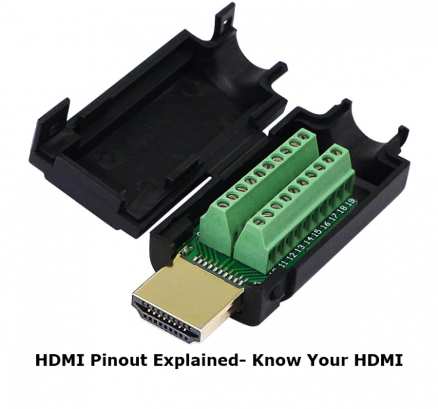
HDMI Pinout Explained
Generally, pins 1-12 carry the TMDS data transmission. It includes video, audio, and auxiliary data information. They form four separate channels for video data, clock data. These data are organized into three categories. They are the Video data period, Data island period, and Control period.
The pins 1-3 carry data channel 2(+ – ground or data shield). Pins 4-6 carry data channel 1(+ – ground or data shield).
Pins 7-9 carry data channel 0(+ – ground or data shield). The pins 10-12 carry the clock data channel that synchronizes the signals (+ – ground or data shield).
Pin 13 carries CEC. CEC establishes bi-directional communication through this pin. And it can connect and control a maximum of 15 devices. The pins 15- 17 carry DDC data. The Pin 14 is kept as reserved for future specification updates. The Pin 18 is allotted to use the 5V low voltage power provided by the source device. Pin 19 is for hotplug detection. It will help the device to reinitialize the DDC when you are reconnecting the cables. It monitors power and plugs and unplugs events.
About HDMI Connector:
There are five connector types in the HDMI system: HDMI Type A, C, D & E. Although Type B is defined, it is not used yet. The pin configuration for every type of HDMI connector remains the same, once they are defined. It indicates that there doesn’t exist any backward compatibility problem.
However, every HDMI connector type has its individual pin configuration. So, when you create cables or design equipment, you need to make sure that you are using the right pin numbers for the different signals.
It is not possible for different HDMI connector types to mate with different types of connectors. So, if you mistakenly cross-connect them, there will not be any problem. You will not face any issues if you have signals on the wrong lines.
The Type A HDMI connector is used for most TVs. Another main HDMI connector type is Type C, which is a mini format. While the mini format is known as the HDMI Type C connector, the micro format is called the HDMI Type D connector. People use the Type E connector for automotive applications.
Format Support:
PAL, NTSC, ATSC, etc., are some major video formats that are supported. You can see videos at up to 1440p resolution or 2560×1440 in progressive format. The highest resolution is 1080p for Blu-ray and HD-DVD. The maximum color depth compatible with up to 120 Hz refresh rates is 48 bits.
The structure of the HDMI cable looks like the popular “twisted pair.” It has several numbers of cores— 19. Connecting an HDMI socket or restoring a damaged connector is possible, once you know the cable’s pinout diagram.
Several people wonder why they need to repair a damaged HDMI connector instead of purchasing a new one. As buying a new cable is far easier. For example, you can buy a 5-meter HDMI cable for 500 rubles and it can meet every necessary modern standard, including:
- 4k support
- 3D support
- High Speed \u200b\u200b with Ethernet.
Think about what would happen if the cable is already embedded in a wall. What will you do if no way exists except to pull the cable out of the wall and replace it? Or are you someone who has a lot of knowledge regarding top-quality brands and prefers using premium HDMI cables only? In that case, you will be able to save money on purchasing a new cable by replacing the damaged HDMI connector.
Pin Description Of HDMI Connector:
Several abbreviations are available for the pinout description of HDMI connectors. You need to know what these denote to understand the signaling of the connectors. Some abbreviations that are included in the pinout are TDMS, CEC, DDC, HEC, HEAC, SCL, SDA, and EDID. Most of them are different communication channels, which are used in HDMI technology. Now, let’s learn about each of these channels.
- Transition Minimized Differential Signaling (TMDS): HDMI cable carries three TDMS data channels. The numbers of these channels are 0, 1, and 2. When it comes to the HDMI Type B connector, the cable carries six data channels. With the help of these channels, you can transmit audio, video and auxiliary data as individual packet types.
- Consumer Electronics Control (CEC): It is mainly for the user’s command and control of up to fifteen devices.
- Display Data Channel (DDC): It is especially useful for the communication between the PC and the display monitor. Display Data Channel communication depends on I2C ( that stands for Inter-Integrated Circuit) bus specification.
- HDMI Ethernet Channel (HEC): The channel permits devices that are connected to HDMI cable to access the internet without using ethernet cables. HEC is transmitted as a differential signal.
- HDMI Ethernet and Audio Return Channel (HEAC): This channel was first introduced in HDMI 1.4. It is used to communicate high-speed bidirectional data. In this case, two pins of the connector were used by it —an unused pin and the hot plug-detecting pin.
- I2C Serial Clock for DDC (SCL)
- I2C Serial Data for DDC (SDL)
- Extended Display Identification (EDID): This one is a signal transmission standard. With the help of the EDID, display devices can communicate with the video source.
HDMI Pinout:
Type A and Type E Connector Pin Assignment:
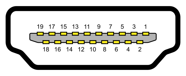
Type A is widely used in many applications. It present in TVs, Recorders, Set-top Boxes Blue Ray disc players and more. The male connector of type “A” external dimension is 13.9mmx4.45mm. And the receptacle or female connector’s internal dimension is 14mmx4.55mm. The A-type connector pinout has two rows of pins with alternate numbering down the length of the connector. Therefore the first row starts with the first pin and ends in the 19th pin. Whereas the second row begins with the 2nd pin and ends with the 18th pin. Type A supports all HDTV modes.
| Row | Pin Number | Pin Assignment |
| Pin 1 | TMDS Data2+ | |
| First Row | Pin 3 | TMDS Data2− |
| Pin 5 | TMDS Data1 Shield | |
| Pin 7 | TMDS Data0+ | |
| Pin 9 | TMDS Data0− | |
| Pin 11 | TMDS Clock Shield | |
| Pin 13 | CEC | |
| Pin 15 | SCL Serial Clock for DDC | |
| Pin 17 | Ground (for DDC, CEC, ARC, and HEC | |
| Pin 19 | Hot Plug Detect | |
| Pin 2 | TMDS Data2 Shield | |
| Second Row | Pin 4 | TMDS Data1+ |
| Pin 6 | TMDS Data1− | |
| Pin 8 | TMDS Data0 Shield | |
| Pin 10 | TMDS Clock+ | |
| Pin 12 | TMDS Clock− | |
| Pin 14 | Reserved Utility | |
| Pin 16 | SDA Serial Data for DDC | |
| Pin 18 | +5 V |
Type B Connector Pin Assignment:
Type B connector external dimension is 21.2 mm x 4.45 mm. It has 29 pins. And it carries six differential pairs instead of three. This type of connector is used for high-resolution displays. It is designed to support resolutions higher than 1080p. However, the use of the additional three differential pairs is reserved. It is electrically compatible with dual-link DVI D. But, it is not commercially employed in any device. The type B connector is one and half times wider. It can carry twice the data as Type A. Type B is a higher resolution version of type A. The Shell will have the dimple for locking.
| Row | Pin | Pin Assignment |
| 1 | TMDS Data2+ | |
| 3 | TMDS Data2- | |
| 5 | TMDS Data1 Shield | |
| First Row | 7 | TMDS Data0+ |
| 9 | TMDS Data0- | |
| 11 | TMDS Clock Shield | |
| 13 | TMDS Data5+ | |
| 15 | TMDS Data5- | |
| 17 | TMDS Data4 Shield | |
| 19 | TMDS Data3+ | |
| 21 | TMDS Data3- | |
| 23 | Reserved (N.C. on device | |
| 25 | SCL | |
| 27 | DDC/CEC Ground | |
| 29 | Hot Plug Detect | |
| 2 | TMDS Data2 Shield | |
| 4 | TMDS Data1+ | |
| 6 | TMDS Data1- | |
| 8 | TMDS Data0 Shield | |
| Second Row | 10 | TMDS Clock+ |
| 12 | TMDS Clock- | |
| 14 | TMDS Data5 Shield | |
| 16 | TMDS Data4+ | |
| 18 | TMDS Data4- | |
| 20 | TMDS Data3 Shield | |
| 22 | CEC | |
| 24 | Reserved (N.C. on device) | |
| 26 | SDA | |
| 28 | +5V Power |
Type C Connector Pin Assignment:
It is a mini connector. And it is smaller than the TypeType A. The plugs’ external dimension is 10.42mmx2.42mm. The Shell of the connector has a spring for locking. Additional springs may be used for EMI reduction. The spring property for locking shall be activated by the locking hole of the plug shell. It also has the same 19 pin configuration as like Type A.
The only difference is it is meant for portable devices. Therefore all positive signals of the differential pairs are swapped with their corresponding shields. The CEC ground is assigned to pin 13. Besides, CEC is assigned to 14 instead of pin 13. Pin 17 is reserved. The Type C Mini connector can be connected to a type A connector using a type A-to-type C cable.
| Row | Pin | Pin Assignment |
| 1 | TMDS Data2 Shield | |
| 3 | TMDS Data2- | |
| 5 | TMDS Data1+ | |
| 7 | TMDS Data0 Shield | |
| 9 | TMDS Data0- | |
| First Row | 11 | TMDS Clock+ |
| 13 | DDC/CEC Ground | |
| 15 | SCL | |
| 17 | Reserved | |
| 19 | Hot Plug Detect | |
| 2 | TMDS Data2+ | |
| 4 | TMDS Data1 Shield | |
| 6 | TMDS Data1- | |
| Second Row | 8 | TMDS Data0+ |
| 10 | TMDS Clock Shield | |
| 12 | TMDS Clock- | |
| 14 | CEC | |
| 16 | SDA | |
| 18 | +5V Power |
Type D Connector Pin Assignment:
| Row | Pin | Pin Assignment |
| 1 | Hot Plug Detect | |
| 3 | TMDS Data2+ | |
| 5 | TMDS Data2- | |
| 7 | TMDS Data1 Shield | |
| First Row | 9 | TMDS Data0+ |
| 11 | TMDS Data0– | |
| 13 | TMDS Clock Shield | |
| 15 | CEC | |
| 17 | SCL | |
| 19 | +5V Power | |
| 2 | Utility | |
| 4 | TMDS Data2 Shield | |
| 6 | TMDS Data1+ | |
| 8 | TMDS Data1- | |
| Second Row | 10 | TMDS Data0 Shield |
| 12 | TMDS Clock+ | |
| 14 | TMDS Clock– | |
| 16 | DDC/CEC Ground | |
| 18 | SDA |
Connector Contact Sequence:
| Signals | ||||
| Connection | Type A & C Connectors | Type B Connector | Type D Connector | Type E Connector |
| First Make | Connector shell | Connector shell | Connector shell | Connector shell |
| Second Make | Pins 1 – 17 and pin 19 | Pins 1 – 27 and pin 29 | Pins 1 – 18 | Pins 1 – 19 |
| Third Make | Pin18 (+5V Power) | Pin28 (+5V Power) | Pin19 (+5V Power) |