
DVI, or the Digital Visual Interface, is a video display interface standard developed by DDWG (Digital Display Working group). It is predominantly used in computers than DVD players and Television Sets. It is a digital flat panel interface introduced by the Digital Display Working Group. Digital Visual Interface is designed to be Plug and Play.
What is DVI?
The digital visual interface connects the display device to the video display controller or the video source. It can be configured to support multiple modes digital-only, analog-only, or digital and analog-only (DVI-D, A, or I). It is further compatible with the Video Graphic Array (VGA) interface. VGA is the last IBM graphics standard. It was indented to create an industry standard for uncompressed digital video content transfer.
Digital Visual Interface specification resolved the industry requirement for digital connectivity for high-performance monitors and digital displays. It further replaces the analog functions on the motherboard for a better visual experience. Besides, it is an open industry standard introduced for higher performance, healthy interfacing solutions for high-resolution digital displays.
In addition, it addressed the core issues of replacing legacy analog technology with digital technology. Digital Visual Interface enhances the user’s visual experience using TMDS (Transition Minimized Differential Signaling). In addition, it has some other advantages over other competing digital display standards such as DFP (Digital Flat Panel), Plug, and Display. However, DVI does not support audio signals. Therefore you need another cable to connect your audio device to the source.
Technical Details of Digital Visual Interface:
Its digital video transmission is on transition-minimized differential signaling. It is based on a Panel link that utilizes the high-speed serial link for video data transmission. DVI connector includes specific pins for DDC (display data channel). Its Display Data Channel uses the DDC 2 version, which allows the graphics adapter to read the monitor’s EDID (extended display identification data).
If the display unit supports both digital and analog signals in DVI-I input, each will host a distinct EDID. Sometimes it will create a problem if the DVI-I port detects both activities, then the display unit is to choose which EDID to send.
When the source and the sink (display unit) are connected, the source will query the display capability from the display unit EDID block. The EDID shares the display identification, Gamma value, color characteristics, and list of supported video modes, native resolution, and designated preferred mode.
Each mode has a set of CRT timing with the specific duration and frequency of the horizontal and vertical synchronization, active display area, vertical and horizontal resolution, and refresh rates. The digitally encoded video picture data is being transported using multiple TMDS links. These links are not affected by electrical noise and other distractions.
Some of the Digital Visual Interface connector pins carry the analog VGA signals. It ensures the basic interoperability of DVI-compliant gadgets. In addition, it ensures the minimum support for low pixel format. This feature ensures backward compatibility with the old displays using analog VGA signals. The video mode uses horizontal and vertical refresh timing, which are compatible with the Cathode Ray Tube display.
TMD Links:
The Digital Visual Interface connection has four TMDS links. Each link has one twisted pair, and each link broadcast data from the source to the sink. The first three pairs are for the RGB components of video signals of a total of 24 bits per pixel. The last one carries the pixel clock data. The data (binary) is encoded using 8b/10b encoding. The data is not formatted into network packets. Instead, they are in vector graphic format (rasterized) analog video signals.
The frames are drawn during each vertical refresh period. The entire active area of each frame is transmitted without compression. The pixel clock frequency is 165MHZ maximum of resolution of 2.75 megapixels @ 60 Hz.
It supports 1920 X 1200 screen resolution @60Hz. In addition, the Digital Visual Interface specification has a provision for dual links.
Moreover, that can support higher resolution display devices. The dual links double the number of TMDS links, effectively providing two times of video bandwidth. Besides, it can support resolutions up to 2560X 1600 @60 Hz.
DVI Cable Length and Specification:
Digital Visual Interface specifications do not stipulate any specification for cable length. Since DVI cable relay on pixel clock frequency cable of length 4.5 meters can work well with the display resolution of 1920 X 1200 @60Hz refresh rate. The cable of 15 meters in length can be used with a display resolution of 1280 X 1024 or less at @60Hz.
If the cable length increases, the display resolution may decrease; therefore, for higher distances, a DVI booster or a DVI signal repeater that has an external power supply can be used to get the higher resolution display. Otherwise, the signal will degrade proportionally to the length of the cable. Good quality cable and the right cable length can eliminate ringing in the signal transmission.
DVI Connector and Its Types:
There are three types of DVI connectors, namely:
- DVI- Integrated combines both digital and analog in the same connector. Further, it may be single or dual links.
- DVI- Analog
- DVA- Digital only; further, it can be of single or dual-link. Sometimes dual links are referred to as DVI-DL.
Other than analog other types of connectors have pins to transmit digital video signals. That too they came in two types, single and double link. In a single-link Digital Visual Interface connector, the video data is transmitted at 165 MHz, supporting the resolution up to 1920 X 1200 @60Hz.
There are another six pins in the middle of the connector in dual links connectors to employ another transmitter to increase the bandwidth and support the resolution up to 2560 X 1600. DVI carries the same type of signal as that of DFP, but their connectors are not physically the same. Instead, DVI comes with 25/29 pins that allow analog signals in addition to a digital signal.
DVI Connectors:
The Digital Visual Interface connectors have pins to transfer the native digital video signals. They are of low-force helix types that have good contact with each other. The DVI connectors have 24 pins in the order of the three-row matrix. Besides, they have added four pins to the right. There are seven different types of ports and connectors, including mini and micro connectors. The single link connectors of the Digital Visual interface do not use pins 4, 5, 12, 13, 20, and 21, whereas dual-link uses all 24 pins. The single link connector uses 12 of the available pins.
Connector Pinout:
Furthermore, the dual-link uses all the available 24 pins. Other than the digital signal, the analog signal is implemented by micro-cross pins C1 to C5. In analog connection, pins 4 to 6, 12 to 16, and 19 to 22 are not connected.
The DVI connectors have four pins to transmit analog signals which can be used to connect an analog monitor. A flat blade surrounds the analog pins on a connector. The analog pins are directly compatible with VGA signaling. In DVI I, you can connect a VGA monitor through a passive adapter. The passive adapters are a simple and very cost-effective solution to support VGA on Digital Visual Interface.
The long flat pin on DVI- D is a little thinner than the DVI I connector. Digital Visual Interface is the only popular video standard that includes analog and digital transmission in the same connector. It uses low voltage differential signaling known as TIA/EIA-644. It is nothing but the technical standard that specifies the electrical characteristics of differential and serial signaling standards.
Digital Visual Interface connectors can transmit an encrypted signal for copy protection using HDCP protocol. Therefore the computer can connect to HDTV sets over Digital Visual Interface connectors, provided the graphics card must oblige and support the HDCP protocol. Mini DVI connectors can be found in Apple computers.
DVI Specification:
- 25.175 MHz- Minimum clock frequency for single link
- 165 MHz- Maximum Clock Frequency for Single link
- 330+ MHz- Maximum clock frequency for Dual-link
- 3.96 Gbps- Data Rate for Single Link without 8b/10b overhead @@ 165 MHz
- 7.92 Gbps- Data Rate for Dual Link without 8b/10b overhead @ 165 MHz
- 4.95 Gbps- Bandwidth for Single Link @ 165 MHz
- 9.9 Gbps- Bandwidth for Dual Link @ 165 MHz
- Pixels per clock cycle 24 bits or less per pixel for Single Link (24 bits per pixel support is mandatory)
- Pixels per clock cycle 25 and 48 bits or less per pixel for Dual Link
- Display Mode of Super Extended Graphics Array (SXGA) is 1280 × 1024 @ 85 Hz with GTF blanking of 159 MHz for a single link
- Display Mode of High Definition TV is 1920 × 1080 @ 60 Hz with CVT-RB blanking of 139 MHz for single link
- The Display Mode of Ultra Extended Graphics Array (UXGA) is 1600 × 1200 @ 60 Hz with GTF blanking of 161 MHz for single link
- Display Mode of Wide Ultra Extended Graphics Array (WUXGA) is 1920 × 1200 @ 60 Hz with CVT-RB blanking of 154 MHz for a single link
- Display Mode of Wide Quad Extended Graphics Array (WQEGA) is 2560 × 1600 @ 30 Hz with CVT-RB blanking of 132 MHz for a single link.
DVI Digital Encoding:
In DVI, video streaming encoding provides a DC balanced output to reduce decoding errors. It is achieved by using 8b/10b encoding. It provides extra bits for DC balancing. The transmission of pixel data and control are separate entities. Therefore the receiver can easily differentiate between active and control regions.
Clock Frequency and DATA:
The data channel of the Digital Visual Interface functions at a bit rate of ten times its clock signal frequency. That is, the clock period is a 10-bit representation per channel. Each set of three 10 bits representations represents one complete pixel in a single link mode, and it is almost half in dual-link mode.
DVI interface provides separate differential pairs for data transfer and clock. Its specification does not allow the clock and data transfer to be aligned. However, the bit rate and clock signal frequency are fixed in the ratio of 1: 10; it is automatically aligned over transmission time. Therefore, the data can be recovered at the receiving sink end using clock/data recovery. Further, this interface allows the input clock to vary between 25 to 165 MHz. I
t makes pixel recovery more difficult at phase-locked loops. The Digital Visual Interface interface can transform the signals from the digital domain into an analog domain using digital to analog converters. Since both clock and synchronization signals are sent over the link, the fixed frequency interfaces need to re construct or realign their clock using the data sent over the link.
Signaling:
VESA Display Power Management Signaling or DPMS is the standard for power management of displays. The DVI also has the DPMS power management system. The DVI specification includes the signaling for the reduced use of power. Generalized Timing Formula is a standard that defines the video parameters such as horizontal blanking, vertical blanking intervals, horizontal frequency, and vertical frequency, signal bandwidth, and polarity.
The analog link helps the standard to be compatible with the previous VGA cables and connectors. Besides, a passive adapter can be used to carry the analog signals between two connectors.
Blanking time is needed for CRT displays. However, LCDs do not need them. However, DVI supports both CRT and LCD, and it includes blanking time overhead in the control details transmission.
HDMI and DVI Compatibility:
Though the Digital Visual Interface and HDMI interfaces use the same electrical specification, such as TMDS, and VESA/DDC links, they work differently in several ways.
HDMI does not include analog signals; therefore, it lacks VGA compatibility.
The HDMI supports YCbCr 4:4:4 and YCbCr 4:2:2 color spaces, whereas Digital Visual Interface supports only the additive RGB color model.
HDMI supports the transmission of data packets in digital audio.
Besides, HDMI standard can differentiate between Legacy DVI displays and HDMI supported displays with the help of Extended Display Identification Data. As a result, interoperability is possible between DVI-D and HDMI devices. HDMI displays can be driven by DVI D since both of them function on overlapping minimum sets of supported resolutions and frame buffer formats.
Some devices use Digital Visual Interface to HDMI adapter to deliver the HDMI signals with audio. Though both interface connectors have 19 pins, Digital Visual Interface can process only the HD video, whereas HDMI is capable of processing HD video, along with eight audio channels.
HDMI is used to deliver both audio and video signals from the source to the sink. However, Digital Visual Interface handles only the video signals. Whereas the other one transmits data from graphic cards to the Monitors, and you need to connect the speaker system externally. HDMI has a higher refresh rate and resolution than the other one.
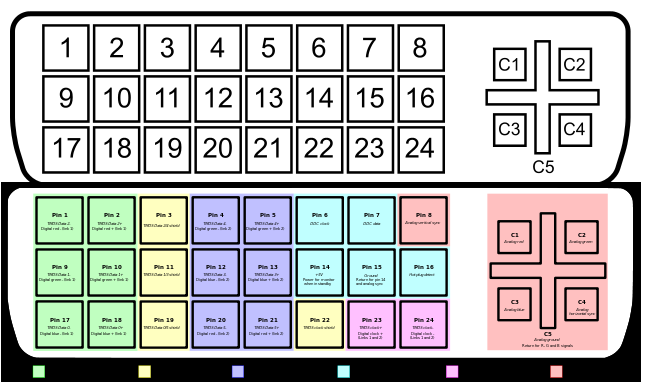
DVI PIN Out
|
DVI PIN Out |
|
PIN# |
Description |
| 1 | TMDS Data 2- |
| 2 | TMDS Data 2+ |
| 3 | TMDS Data 2/4 Shield |
| 4 | TMDS Data 4- |
| 5 | TMDS Data 4+ |
| 6 | DDC Clock |
| 7 | DDC Data |
| 8 | Analog Vertical Sync |
| 9 | TMDS Data 1- |
| 10 | TMDS Data 1+ |
| 11 | TMDS Data 1/3 Shield |
| 12 | TMDS Data 3- |
| 13 | TMDS Data 3+ |
| 14 | +5V Power |
| 15 | Ground |
| 16 | Hot Plug Detect |
| 17 | TMDS Data 0- |
| 18 | TMDS Data 0+ |
| 19 | TMDS Data 0/5 Shield |
| 20 | TMDS Data 5- |
| 21 | TMDS Data 5+ |
| 22 | TMDS Clock Shield |
| 23 | TMDS Clock + |
| 24 | TMDS Clock – |
| C1 | Analog Red Video Out |
| C2 | Analog Green Video Out |
| C3 | Analog Blue Video Out |
| C4 | Analog Horizontal Sync |
| C5 | Analog Common Ground Return |